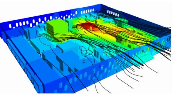
This week’s blogg post from Volupe will be a continuation of an earlier week’s introduction to wizards and add-ons in Simcenter Star-CCM+ (https://volupe.se/wizards-and-add-ons-in-simcenter-star-ccm-part-1/). While, last time was focused on the wizards, where you basically get help when facing a specific problem, this week we will look at the Electronics Cooling Toolset add-on. In this tool you are provided with the possibility of importing IDF (relating back to lasts week description of the IDF Import wizard) but also ODB++ (open database). The toolkit provides a simplified approach withing Simcenter STAR-CCM+ to perform simulations of thermal management for electronic devices.

Electronic cooling toolkit
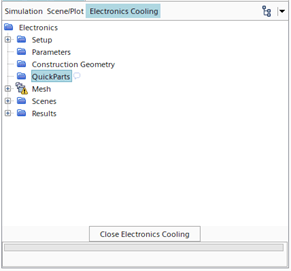
The Electronic Cooling Toolkit (E-cool) is a tool in Simcenter that does not require an additional license. The toolkit is activated by clicking WindowàToolbarsàElectronics cooling or by dragging and dropping the electronic cooling symbol from the customize option.

Once the symbol is in the toolbar you can click it to activate the specific GUI options. In the additional window that opens you have a customized tree with some additions specific to the electronic cooling toolkit.
The main features of the Electronics Cooling Toolset are:
Geometry
- Geometry generation that is based on simple shape templates
- Import of IDF (Intermediate Data Format) and ODB++ (Open Database) files
- Import of CAD models from other CAD packages
- Transfer of CAD data from the Simcenter STAR-CCM+ CAD modeler
Physics
- Time: Steady-state calculations
- Solution domains: multi-domain (fluid and solid)
- Heat transfer modes: conduction, convection (forced and buoyancy driven), and radiation (wavelength independent Surface-to-Surface (S2S) radiative heat transfer)
- Flow regime: laminar or turbulent (Realizable K-Epsilon Two-Layer All Y+)
- Equation of state: constant density or ideal gas
Conditions
- Environment: ambient boundary conditions
- Thermal specification: specification of material or specification of layers (PCB)
- Compact thermal models: resistor networks for chips
- Heat dissipation: volumetric heat sources
Mesh
- Volume Mesh: Trimmed cell mesher generates predominantly hexahedral cells
- Prism Layers: prismatic cells on walls for boundary flow accuracy
- Cell size: automatic calculation of target and minimum cell size that is based on overall model size
- Mesh Refinement: integrated features for mesh refinement to detect and capture complex geometries
- Local mesh controls: cell size customization on surfaces and within volumetric zones
Solve
- Segregated solver for flow and energy
- Solver under-relaxation
- Live monitoring of solution data
Results
- Visualization of geometry, scalar, and vector quantities
- Access to solution data through streamlines, isoosurfaces, and plane sections
- Residuals and XY plots
- Summary reports
Chip modelling
The Electronic Cooling Toolkit provide simplification for the simulation of chips. The possible level of details for a chip are immense and is best simulated using some sort of assumptions.
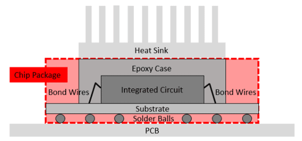
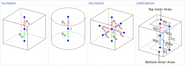
The first approach is to simulate the chip as a solid model, then you have a solid part, made of a specified material. The excess of the heat is simulated using a total heat source of the part. The other option is to use a Compact thermal model (CTM). That model represents the critical heat flow path inside the package using a thermal resistor network. Every node in the network corresponds to a surface of the package or region withing the package and is associated with a single temperature. The CTM method is more accurate than a solid model. It does not require a volume mesh inside the package, also making it computationally less expensive. It requires access to the details regarding the heat flow within the package. The following types of resistor networks are available in Simcenter STAR-CCM+:
PCB modelling
A PCB (Printed circuit board) is usually the board that your chips are located. It is often built from several layers containing different fraction of cupper for increase is conductivity and heat transfer. Also, here you can choose a simpler approach with a simple solid, perhaps given an anisotropic conductivity to account for the appearance of the cupper within each layer. The other option is to use a detailed approach and represent the PCB as a composite of multiple layered solid parts.
Modelling the thermal conductivity of each layer can be by either specifying the metal fraction of metal in each layer. The thermal conductivity is isotropic throughout the layer and calculated as a function of the metal fraction and the thermal conductivities of the metal and the dielectric material. The other option is to specify an image-file, import a bitmapped image that represents the layers metal content. Then based on image grayscale, the toolkit localizes the metal and creates a thermal conductivity map. This map is then converted into a table and mapped onto the volume mesh of the respective layer.
Note that there is an extensive best practise guideline for electronics cooling on support center, and that can be found following the link. And if you wish to test this, there are tutorials on this in the tutorial package associated with Simcenter STAR-CCM+ and a quick overview in the video tutorial below.
I hope this has given you a brief introduction to the possibilities of simulating electronics within Simcenter Star-CCM+. More information can be obtained in the documentation. And as usual, if you have any questions, do not hesitate to reach out at support@volupe.com.
Read also:
How to set up the wizard in Simcenter FloEFD
Simcenter Flotherm™
Products – Siemens Simcenter Software
Blog posts Volupe


