Parametric Modelling with Simcenter STAR-CCM+
Simulation helps us to drive engineering innovation. And the, by far, most important tool for that is design space exploration. However, modelling real-world behavior of complex systems with an increased number of input factors opens an overwhelmingly large design space of possible innovations. To manually find your best fit is virtually impossible and that is why we have a variety of search strategies, e.g., the SHERPA optimization algorithm or Latin Hypercube sampling (both available in Simcenter STAR-CCM+ Design Manager), to explore the design space. But the best algorithm is toothless if our model is not built in a parametric fashion. We will therefore take a closer look in this week’s blog at the approaches in STAR-CCM+ the set up a parametric model.
STAR-CCM+ gives access to a wide range of input parameters that can be exposed and driven in your exploration studies.
What is a Design Parameter
Let’s start with the first type of parameters called Design Parameters. A design parameter is a reference variable that you can use to define model dimensions and feature sizes.
In 3D-CAD
For geometries built directly in Simcenter STAR-CCM+ (the embedded 3D-CAD modeler), you can create Design Parameters of different geometry properties (defining the units). Each design parameter has a name and a value, which can be can be accessed in sketches.

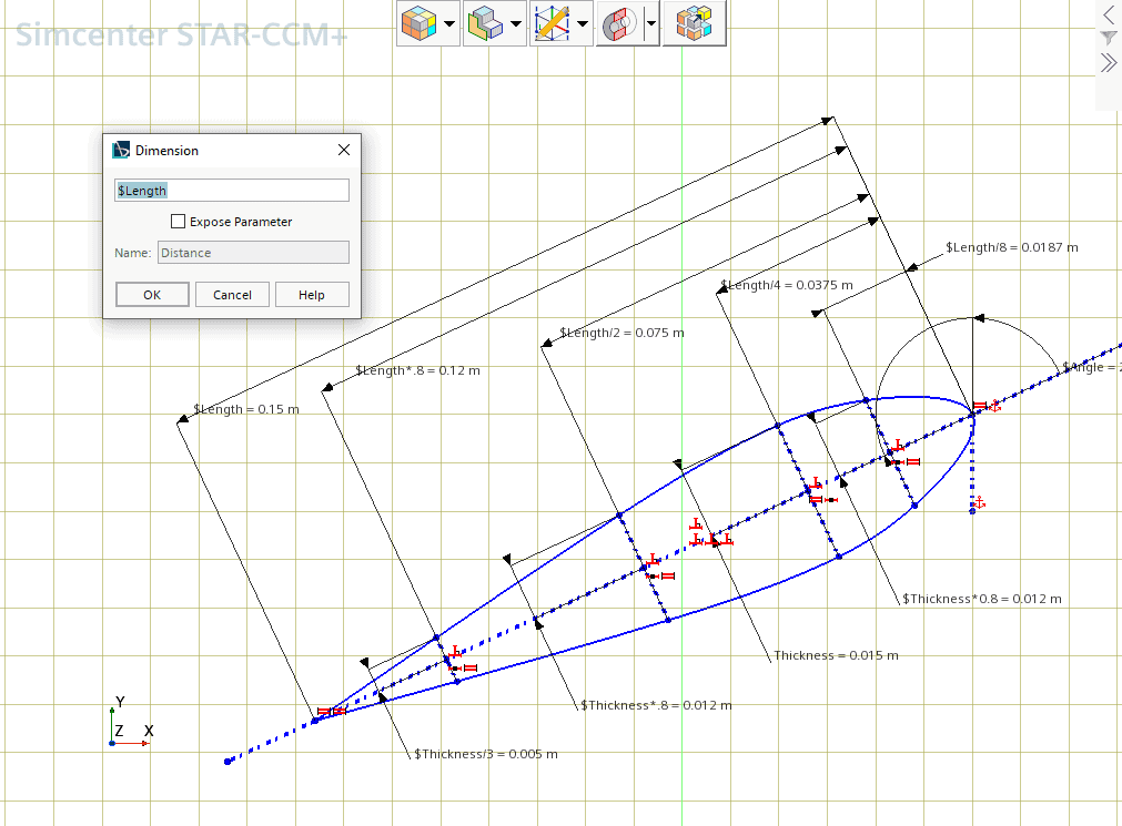
When you enter a parameter name into a dimension dialog, for example, the dimension is set to the corresponding value of the design parameter. Design parameters are versatile, and you can use them to form larger expressions e.g., $Length*0.8. This means that you can enable create a fully parametric model of your geometry and control it in a design space exploration.
CAD Client
If you prefer to use your own CAD package, the CAD Clients add-on licenses will allow you to access and pilot these external CAD parameters. In Simcenter STAR-CCM+ we call them CAD Clients parameters. This bi-directional transfer of information between your external CAD package and Simcenter STAR-CCM+ is available for NX, CATIA, Creo and Inventor.
Freeform modelling
But what if you have a model that is neither parametric nor build in 3D-CAD? Well, in that case 3D-CAD still can help to parametrize you geometry with the Freeform surface modelling. This is a modelling technique in 3D-CAD that allows you to deform existing surfaces for desired shapes. And again, you control the deformation by a Design Parameter.
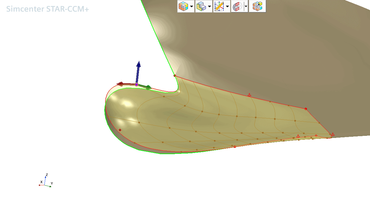
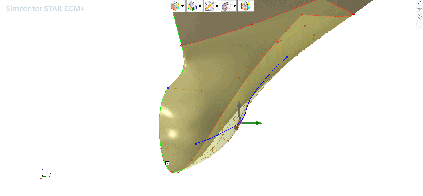
Here we have classical example for Freeform modelling: The bulbous bow of ship. Ship bulb optimization is one of the most common applications related to design exploration in the marine industry, as it is well-known that by working only on the bow geometry it is possible to have quite a huge impact on the overall resistance, and hence ultimately fuel consumption. Practically, you can alter the shape of your geometry and deform multiple connected faces simultaneously.

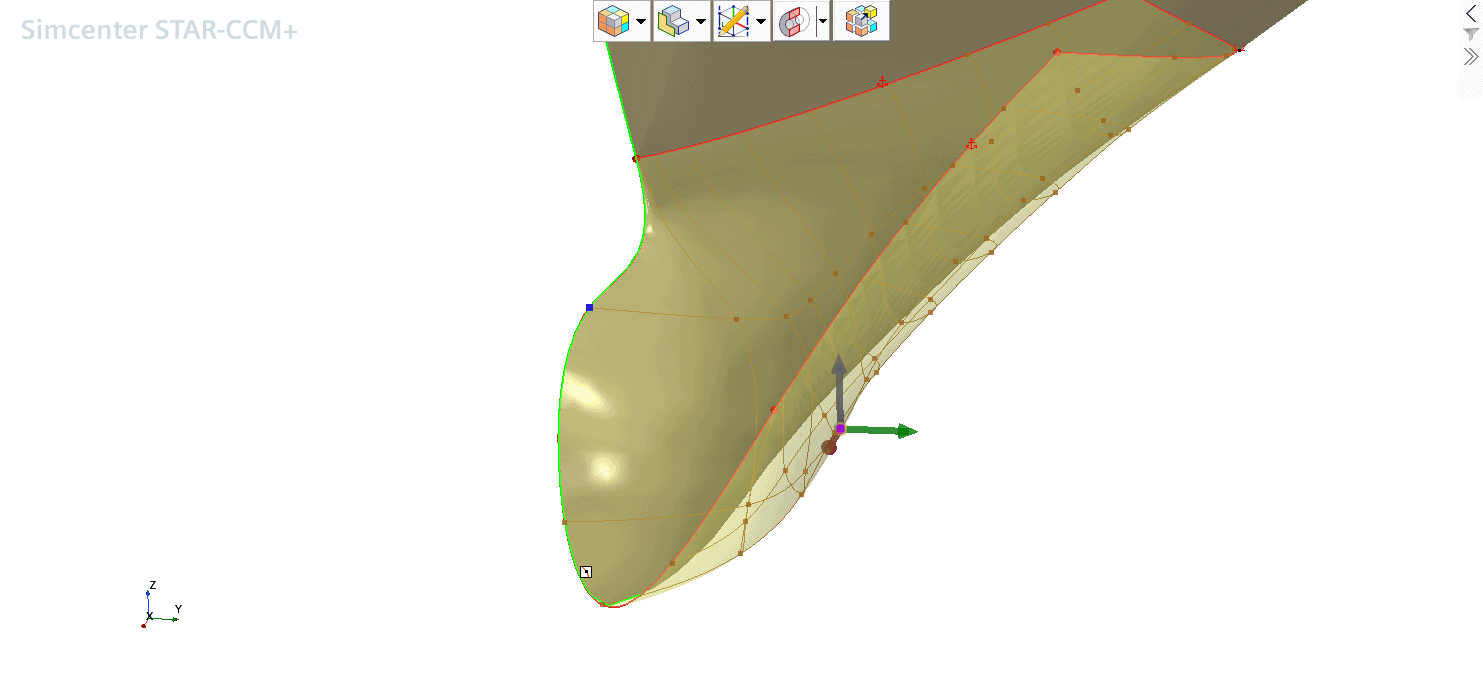
Controlling the deformation of the freeform surface is simple by using control points. In the figure above I simply used a single control point the change the shape of the entire bulbous bow. This is also very “optimization friendly”. But, you can also use Line on Surface or Spline on Surface. Moving a point on a line or spline respectively will then extend the influence of the deformation towards the other points on the same line (see the following figures).

Boundary constraints control the behavior of boundary edges on the freeform surface (that is, edges that bound the freeform surface).
Fixed edges constrain the boundary so that it cannot move. This option is used to maintain the shape of the boundary edge.

Tangent with Current Face maintains the tangency with the initial surface at the specified boundary edges. This option is useful if you want to maintain tangency with the specified edge of the current face. While Tangent with Adjacent Faces creates a tangency between the freeform surface and adjacent faces. This option is useful for making the freeform surface blend into the surrounding surfaces. This option modifies consequently also the neighboring faces.
Please refer to the manual for the explanation of yet a handful other possible boundary constraints. And find below a detailed video tutorial of application of Freefrorm modelling on a bulbous bow, enjoy!
What is a Simulation Parameter
A Simulation Parameter is also referred to as a Global Parameter and can hold scalar physical quantity that can be defined once and used to set multiple properties in your simulation.
One application of a global parameter is in defining a key physical characteristic as a reference value. Other values can point directly to this reference value or be defined in terms of it. For example, in your analysis of a rotating machinery the rotation speed of the pump could be set once as a global parameter, and then be used by Design Manager to vary the rotational speed and create a pump performance curve. You can virtually use Simulation Parameters everywhere, where you can click the “…” button.
What is a File Path Parameter
Finally, there are File Path Parameters which can store path information to a geometry. This can be used within the Replace Part operation. Manager can pilot this parameter as well to drive a part replacement in your exploration studies.
I hope that this helps you to get the best outcome of you Simcenter STAR-CCM+ to fulfil your simulation tasks easier! As usual, do not hesitate to reach out to support@volupe.com if you have any questions.
Find more interesting reads on automation and parametrisation:
Simcenter STAR-CCM+ and NX CAD client
STAR CCM+product page


