This week we will take a closer look at the settings for using fluid-structure interaction (FSI) in Simcenter STAR-CCM+. This blog post is inspired by the tutorial Diaphragm valve, found in the documentation for the latest release of Simcenter STAR-CCM+, 2021.2 (you find the tutorial under Solid stress).
FSI is when you have a two-way coupled interactions between a solid domain and a fluid domain. For example, the solid can be flexible and moving in a fluid. Then the resistance of the fluid will deform the solid. Since the velocity field of the fluid will be dependent on the solid’s location and motion, a two-way coupled interaction is describing the physics of the coupled system.
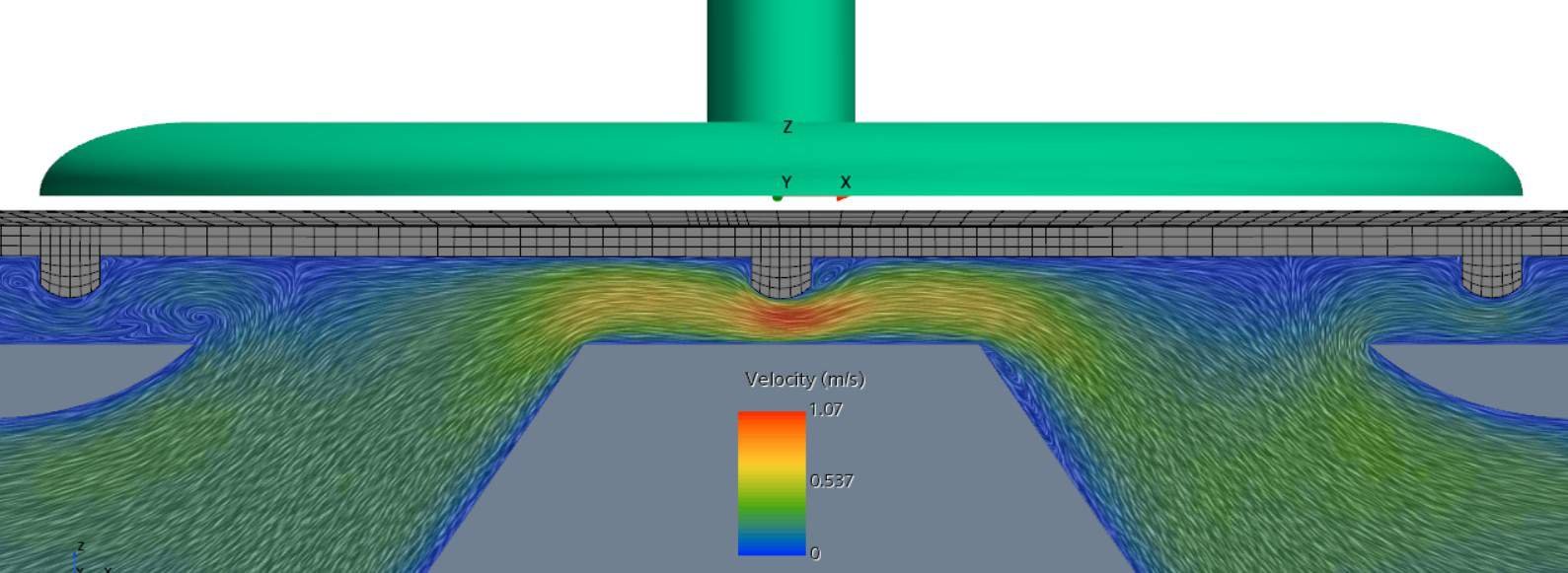
When reading this blog post you can have in mind a flexible solid that bounces on a wall, while fluid is flowing around the solid. To be able to model this system we need a geometry of the solid and one for the fluid domain. The solid will need one mesh operation, and the fluid will need a separate one. The motion of the solid requires an overset mesh (morphing and remeshing is another way to simulate the solid movement, but in this article we focus on overset mesh). Since the solid will be in contact with the wall, the overset mesh will be of the type overset mesh zero gap. The overset mesh with the zero gap feature can deactivate cells to close the last cells between a wall and the overset object, and then activate the cells again when the gap increases.
Meshing
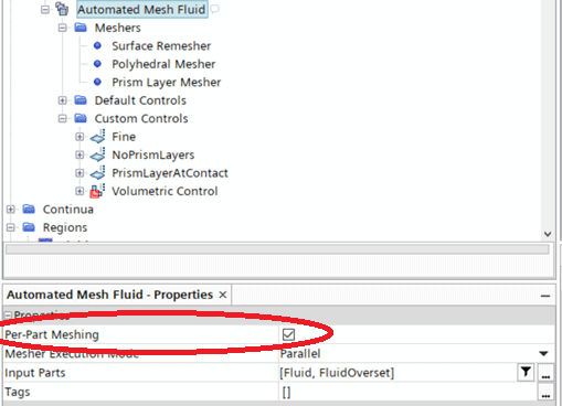
The background fluid and the overset mesh region is possible to mesh in the same operation, by using the per-part meshing procedure. This helps both meshes to become similar in size. If the cells of the two meshes are very different in size, you will receive an error message and the simulation will be aborted. Use Custom controls to create refinements close to the body of interest.
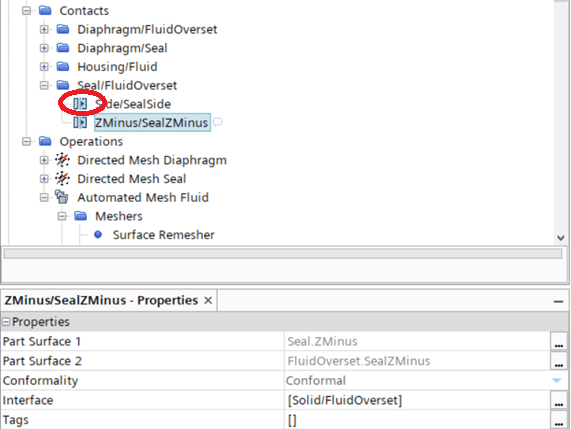
For the meshes to communicate with each other, contacts are needed. The icon for the contact indicates which type of contact it is. The contact will be connected to an interface.
Interfaces
In the picture below there are three different interfaces. The icon shows that the first one is between two solids, since there are two grey rectangles (this will not be needed if you have a simulation with only a bouncing solid). The second icon shows the overset mesh where you have four features possible to enable. The default settings of all these options disabled should be tried first. The setting of treating error as warning is not recommended to use. If the region hierarchy (where FluidOverset as highest priority, meaning that it should provide information to the region Fluid) is wrong, you change the hierarchy by right-clicking on the overset interface and choose swap regions. The third icon shows that this interface is between a solid and a fluid region.

Boundaries
When it comes to the regions, the background mesh is almost as a regular flow simulation, only that a zeroGapWall boundary is automatically added. In this boundary, cells that are currently inactivated due to the zero gap feature, will be stored temporarily.
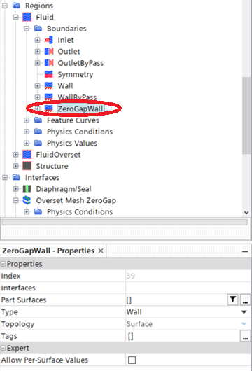
The overset region will also have a zeroGapWall boundary. There will also be an overset boundary which you as a user set by selecting the boundary between the background and overset mesh, and selecting the type to be overset mesh. There will also be an interface boundary for the active FSI interface, which maps the information calculated by the stress/fluid solver.
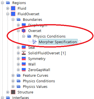
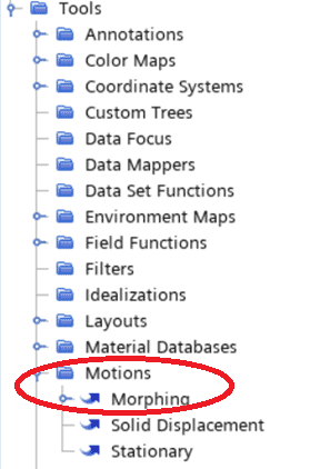
Motions
Note that the morpher specification of the overset region should be floating as this region will change. By creating motions under Tools this option will be available. The motion “Morphing” is set at the motion specification under physical values for the region. For the solid region the motion specification should be set to solid displacement.
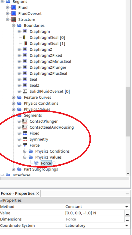
Structural set up
For the solid region there will be the possibility to set constraints and load, by adding segments. Create surface segments by right-clicking on the solid region node and select create segment. The constraints symmetry and fixed are constraining the displacement of a surface. The constraint rigid contact can define a plane which is preventing the solid’s motion. Here you also define a penalty contact enforcement which is a value of how elastic the bounce should be. A larger penalty allows for a smaller non-physical penetration, but a smaller penalty ease the convergence. The penalty should therefore be as large as possible, within the convergence limit. For the load, you can for example specify a force, just remember that a force is always a vector (this can be good to remember if you would like to describe the force as a field function).
Also make sure that the interface boundaries (for both the overset and the solid region) have the correct FSI coupling specification. This physical condition show which physical properties are calculated and then used as input to this region. For the overset region solid deformation will be used, and for the solid the coupling should be set to fluid load if two-way coupling is wanted.
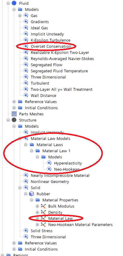
Models
For the models, described in the continua, we have the ones for the fluid that are describing a single-phase fluid with turbulent properties. Since we are using overset mesh the model overset conservation is added automatically. For the solid we are modelling an elastic material, therefore the material law models need to be added, and then referred to in the material properties of the solid material (further down in the same continua under material law).
Now you are ready to run your FSI simulation!
We from Volupe hopes that this blog post has been helpful for you to understand what is essential to specify in a FSI simulation. Hopefully the overset mesh technique is a little bit clearer as well, and how to use these features together. If you have any questions about this post or your simulation, please feel free to contact us at support@volupe.com.
Author
Christoffer Johansson, M.Sc.
support@volupe.com
+46764479945