Some weeks ago, we discussed turbomachinery simulations for one sector analysis in Simcenter STAR-CCM+ in the Volupe blog, https://volupe.se/en/turbomachinery-features-for-one-section-in-simcenter-star-ccm/. This week we will dig even deeper into this topic and explore the Turbomachinery workflow (an add-on to Simcenter STAR-CCM+) that Siemens have created to ease your everyday work, for turbomachinery applications. We will show both how to get started with the workflow, and also some of the benefits of using it.
What is the turbomachinery workflow?
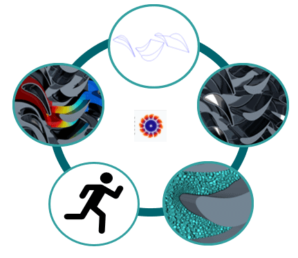
The turbomachinery workflow will help you transform curves representing your geometry, to tessellated geometry, to a meshed fluid domain, to a simulation and finally to automatized post-processing – with a streamlined strategy. You can see the visualization of the workflow in the picture below, going from curves at the top of the picture and executed in clockwise direction, where the icon for the workflow is attached in the middle of the picture. When the workflow is installed, this icon will be visible in the Simcenter STAR-CCM+ GUI.

How to install the turbomachinery workflow
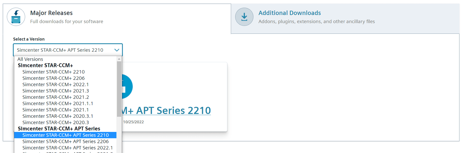
To install the workflow, you go to Siemens Support Center and select Simcenter STAR-CCM+ > Downloads and go to Simcenter STAR-CCM+ API Series as in the picture below.
Note: There are several workflows that you can download in the API series, such as Hull performance workflow and Mixing vessel workflow. You will find them all at this location in Support Center.
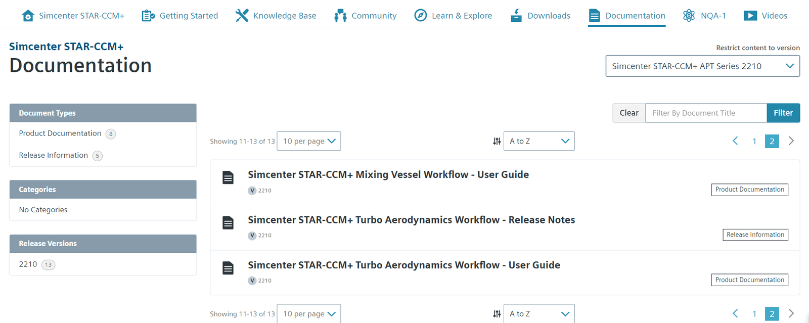
Here you will find a zip-file named Turbo_Aerodynamics_Workflow, which includes all files for the add-on to Simcenter STAR-CCM+ to run the workflow – together with an example file and a geometry to run simulations on. It is described how to install the add-on in the workflow User guide. The user guide is found in the documentation tab, which can be seen in the picture below.
How to import your geometry into the workflow
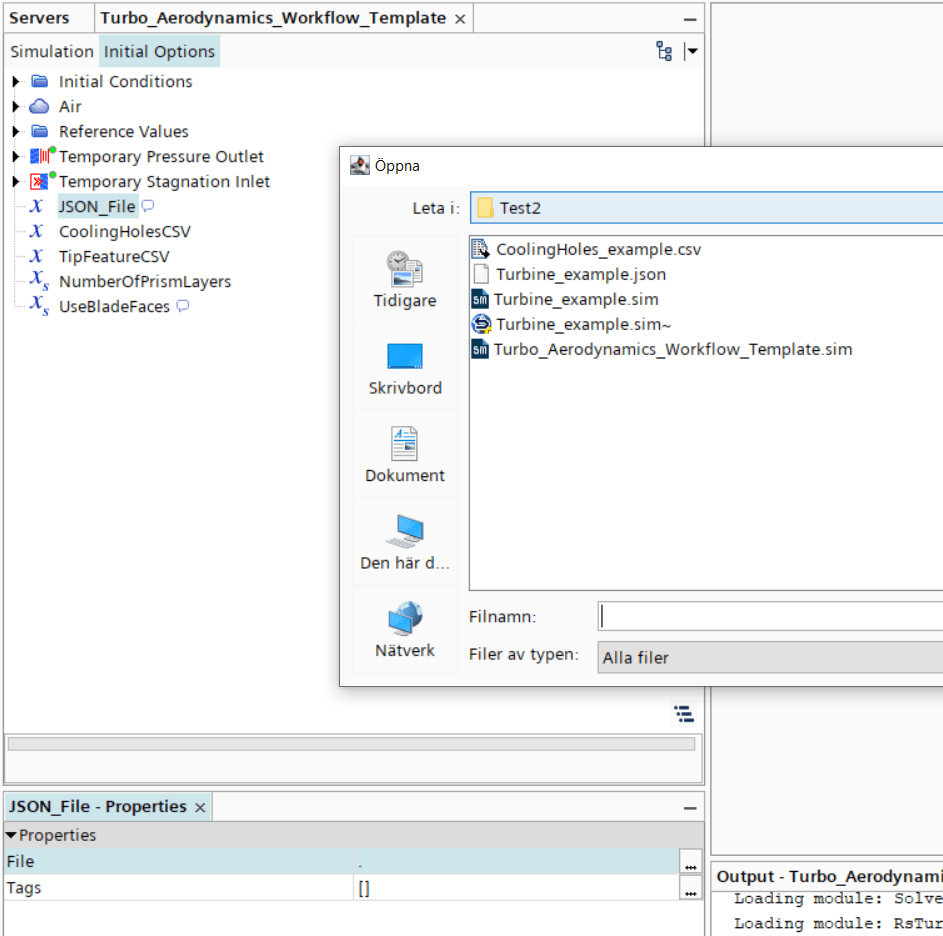
When the add-on is installed, you can open the Turbo_Aerodynamics_Workflow_Template.sim in Simcenter STAR-CCM+ to reach the starting-file for the turbomachinery simulations. This sim-file is only possible to open in serial mode. In the template you specify all your flow parameters, and your geometry. You import your geometry as curves via a .json-file, see picture below. The name of the .json-file will define the name of the simulation file which is generated from the workflow – which you later will mesh and run the simulation on. From the newest release of Simcenter STAR-CCM+, version 2210, you can also import .csv-files for geometry changes such as cooling holes and squealer tips. When your flow parameters and geometry are specified, you can generate the actual simulation file by clicking the icon for the turbomachinery workflow in your GUI.
Note: if you already have a simulation file with the name that will be generated from the .json-file you will get an error.
Meshing and running the simulation for the generated simulation
The workflow will give you a simulation that is ready to mesh and run. In the example file you will have a rotor and a stator which are connected with a mixing plane (a mixing plane is a type of interface that will average the solution between the rotor and stator since you often have different number of blades in the two components). The boundary conditions are already defined based on the settings in the template file.
When it comes to the mesh settings you will obtain an automated mesh operation as default, with calculated values based on the geometry. The near wall thickness (the first cell height) in the mesh will therefore give a y+ value that hopefully fulfills your need in terms of refinement. Since the y+ value is dependent on the velocity field as well as the mesh, the workflow can only aim for a certain type of mesh. The workflow is set to aim for a low y+ approach (with values for y+ around 1), but the All y+ method is used if y+ = 1 is not acheived at all locations. The automated mesh operation results in a mesh with polyhedral cells. See the picture below for y+ values generated with the default settings.
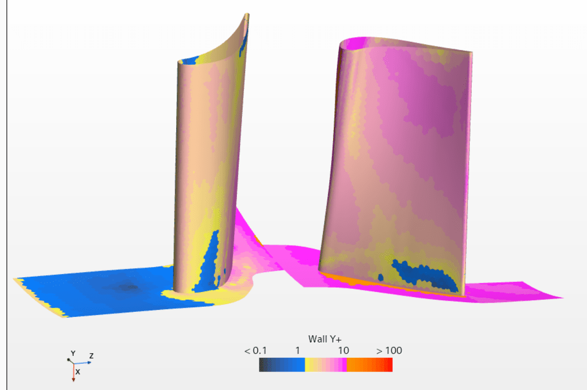
Note: You can of course swap to another mesh operation and define your own mesh settings as well. If you want to run an axial turbine simulation, you could benefit from using the Turbomachinery (structured) Mesh discussed in the previous blog post mentioned earlier.
The continua default settings are to use steady state, k-omega turbulence model, ideal gas and coupled solver. These settings are of course also possible to change if you, for example, want to run a transient simulation. If you are interested in the transient results for a fully developed flow, it can be a good idea to run the steady state simulation first and use it as an initial guess for your transient simulation.
Automatized post-processing
The greatest benefit of the workflow is probably all the post-processing that is automatically obtained. You get:
- Derived parts: Both for mesh evaluation in terms of thresholds for quality and also surfaces and volumes to use for evaluation of results.
- Reports: Everything from positions to flow features to computational information.
- Monitors: Grouping of all monitors, both default monitors for residuals and monitors corresponding to the reports, is organized.
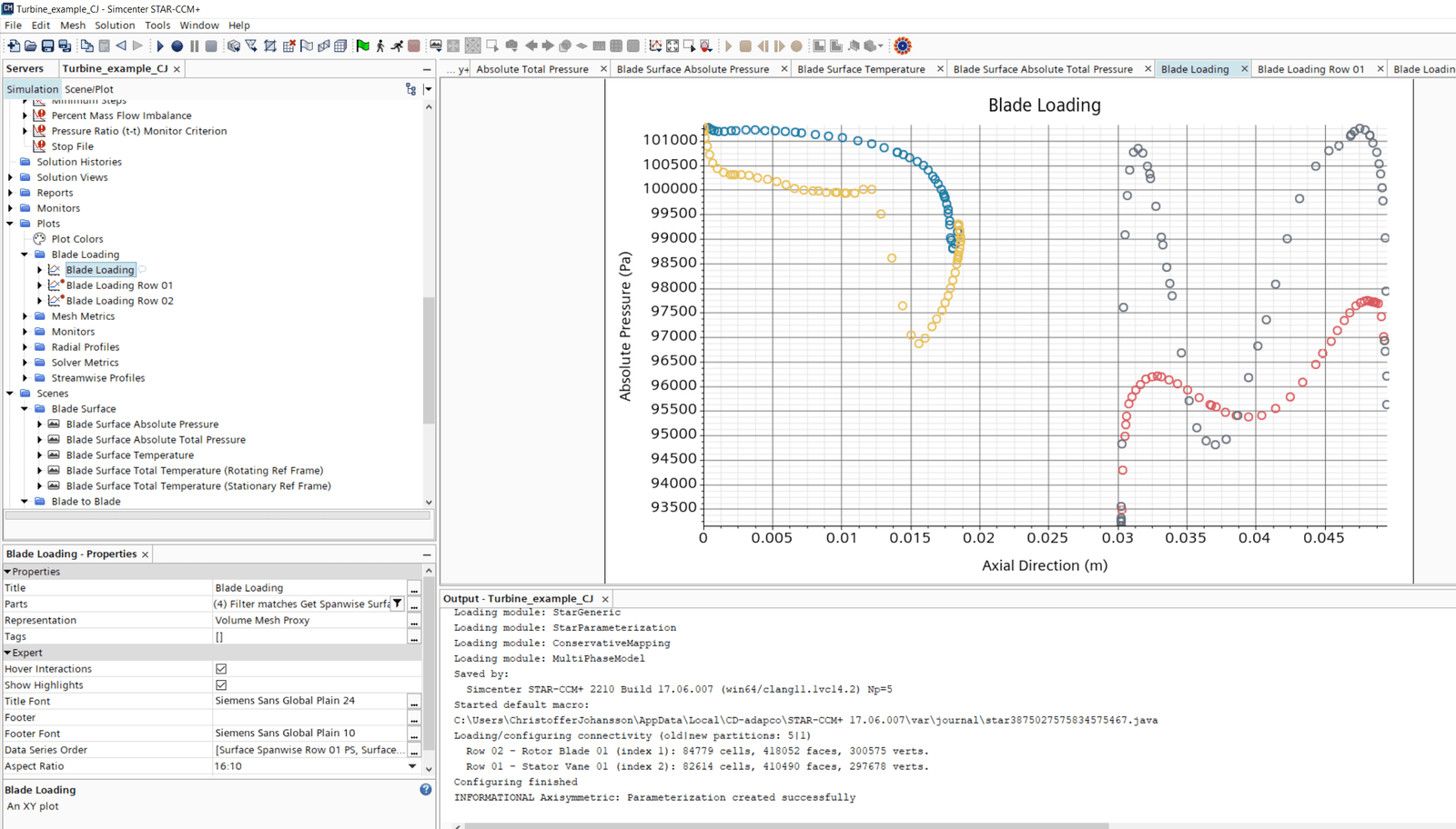
- Plots: Plots for all reports and also flow related reports like blade loadings are pre-defined (in the same way as described in the previous blog post for turbomachinery). See picture below for an example of a plot visualizing blade loading, for both the stator and rotor.
- Scenes: Scenes visualizing everything from geometry, to mesh features, to blade parameters, to spanwise flow features.
- Field functions: Pre-defined field functions will be found for everything from geometry related features to swirl of the velocity field.
- Parameters: All parameters that are used can easily be reviewed and changed (if needed) in the Parameter folder in Tools. The parameters are used in the simulation as dynamic queries.
In the documentation, all reports etc. are explained, so the user can benefit as much as possible from all pre-defined settings. But hopefully most available features will be organized and self-explanatory – so you as a user will understand it without reading about the definitions!
We at Volupe hope that this blog post regarding the turbomachinery workflow has been of interest for you, and that you can go from curves to post-processing even faster from now on. If you have any questions regarding the workflow, or any other technical question, you are welcome to send them to support@volupe.com.
Author

Christoffer Johansson, M.Sc.
support@volupe.com
+46764479945


