One of our goals as design engineers is to get close as we can to reality when doing simulations of a prototype. By simulating fluid dynamics you can get a good prediction of how a prototype performs. To take this one step further, we can also predict the stresses in a structure and how they will deform it. A hydrofoil would be a textbook example for Fluid Structure Interaction. Simcenter STAR-CCM+ comes with an integrated solid stress solver which makes it straight forward to connect your flow simulation with finite element analysis. However, in some situations a one-way coupling would be sufficient, and you might want to decouple the stress analysis from the fluid flow simulation to make changes to the structure. In those cases, the Simcenter STAR-CCM+ File Import/Export option comes in useful. Even if you perform the analyses with Simcenter STAR-CCM+´s solid stress solver. Let´s have a look in this week’s blog on how we can export and import fluid loads on the example of a marine propeller simulation.
General Setup and differences to direct coupling
Simcenter STAR-CCM+ allows for fully defined fluid and solid domains with a coupled exchange of data (1-way or 2-way coupling) as shown in https://volupe.se/en/marine-fsi/. These couplings can be defined as Explicit coupling of the models (data exchange occurs once every x units of time), or as Iterative coupling of the models (data exchange occurs multiple times per time step).

However, if you want to simulate the stresses completely separated, either in another tool or consecutive to the flow simulation, Simcenter STAR-CCM+ allows you to export and import data files streamlined with External Links framework. This way you can store the flow results (even transient data) and analyze individually, such that you can run with different material properties, without the need to re-run the flow simulation.
Here we exemplify the setup for the transient simulation of the Potsdam Propeller Test Case (PPTC). The corresponding CAD is available in the Tutorial section. The aim is to simulate the stresses in the propeller at the initial phase when the propeller is started. Eventually, we can repeat the stress analysis with different material settings.
Both stress and flow analysis are carried out by Simcenter STAR-CCM+, yet in two separated simulation files. The transient CFD simulation saves the pressure on the surface to CGNS mesh and data files. The FEM simulation file imports the pressure and maps it on the solid mesh for the stress analysis.
To achieve a stationary representation of the rotating propeller, we pass the pressure on the rotating propeller through a proxy region, from where it is exported to CGNS files at each time step trigger. The proxy region can be a copy of the rotating region at time = 0, or ideally have the same mesh as it will be used for the FEM calculation. To account for the motion in the solid stress calculation, we apply a rotating reference frame.
On the import side, we set up a simulation for solid stresses only and map the fluid pressure on as a load on the propeller.
Data Transfer via CGNS
External Links framework uses coupling through CGNS files. As the CGNS standard is widely used by a variety of software packages, CGNS import/export enables data exchange between Simcenter STAR-CCM+ and external software.
Simcenter STAR-CCM+ allows you to:
- Export mesh and solution data from regions or boundaries to a CGNS file.
- Import mesh and solution data from a CGNS file and apply it to regions or boundaries.
In the section below we will go through both options.
1. Setting up Simulation for CFD and Exporting Data
You require an additional physics continuum with the File Import/Export model. This continuum represents the external CGNS file and is not related to the physics that are solved in the Simcenter STAR-CCM+ simulation. This means in our case we have three Physics:

- The second (Physics 2) is added to the tutorial setup to enable the file exchange.
- The third (proxy) is added to create the proxy region to map the pressure to a stationary mesh.

In the newly created External Links node we must specify what we want to export. Here we export the mesh from the proxy region onto which we mapped the pressure (field function MappedPressure from Tools > Data Mapper). In the Conditions sub-node, we have setting for the export trigger and the option to restrict the export to a certain range of time.
2. Setting up Simulation for FEM and Importing Data
To compute the stresses on the propeller blades, we import the pre-recorded fluid loads from the CGNS files and apply them to the solid propeller. The imported CGNS files are a subset of the fluid loads recorded in the transient fluid simulation. The subset contains data between 0 and 5 seconds.
Let’s assume we have already prepared the simulation file for a solid stress analysis of our propeller. This means the simulation already contains a physics continuum that models the solid propeller. For the import, again, we need a simple continuum for External Application to activate External Links node.

In the Conditions node of the link, we need to set the import direction to Import and the trigger for import to the Time Step. Then we can select the following setting:
- Time Interpolate for Timescale Control.
Allows you to control how the CGNS timescale is mapped onto the current timescale.
Time Interpolate linearly interpolates between current solution state and CGNS solution state. - Time Range to Enable Between Start and Stop times.
Allows you to either restrict the data import to a specific time range or adjust it to CGNS time scales (that was recorded). - Mapping Option to Map After import.
Automatically map the imported data to the computational domain after import.

Once the Link > Condition and Values are defined, Right-click the External Links > Link 1 node and select Scan: All CGNS states will appear in Import Link State.

With the fluid pressure files being scanned, right-click the Link 1 node again and select Create External Parts. Two regions and Link 1 > Zones will appear according to the export settings.
Right-click Link 1 and select Import Meshes.
To apply the fluid loads to the solid region, you map the loads from the fluid mesh defined in the CGNS files to the solid mesh (solidPropeller). Select the External Links > Link 1 > Zones > Rotating Region proxy Blades > Conditions > Surface Parts and select solidPropeller.propeller. The same holds for the hub.

Now we can Right-click Link 1 to Import Fields to plot the MappedPressure on the solid.Propeller region:

Last step is to apply the fluid loads from the CGNS files to the solid propeller region. Loads are applied by segments. Segments are Simcenter STAR-CCM+ objects that define loads and constraints on solid parts in stress simulations.
Based on the pressure applied via the segment, Simcenter STAR-CCM+ computes the solid stress throughout the propeller. Here we create two segments, one to fix the propeller on the backside of the hub and one for the fluid loads. For the fluid loads select the Field Function Co-Simulation: MappedPressure. As we set the Mapping Option to Map After Import Simcenter STAR-CCM+ automatically maps the imported fluid pressure to the solid mesh and applies the mapped data to the surfaces that you specified using the segment.

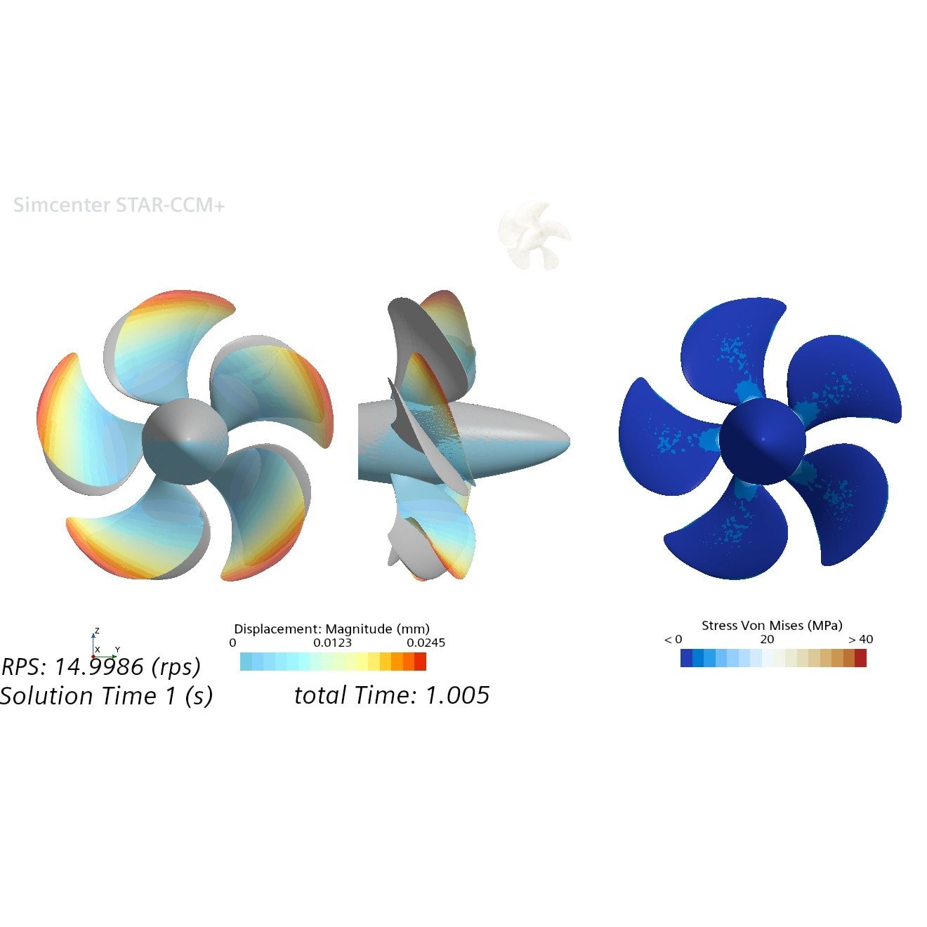
Results
The outlined approach for one-directional FSI allows you to decouple your CFD and FEM analysis. For example, with one CFD run we can study the impact of the propeller material on the stresses and deformation. As we did here for a propeller in Stainless Steel, Aluminum, or Naval Brass.


We at Volupe hope that this blog post gives you an idea about the FSI coupling options and potentially allows you to find design alternatives faster. For more details on FSI and how to find better designs faster or if you have any questions you are always welcome to reach out to us at support@volupe.com.
The Author
Florian Vesting, PhD
Contact: support@volupe.com
+46 768 51 23 46


