In this week’s blog post we are going to have a closer look at conformal meshing. Conformal meshing is when the cell faces on a surface exactly align with the cell faces on the surface other side of a boundary/interface – meaning that the mesh nodes are located on the same point. For some numerics solved by Simcenter STAR-CCM+ this becomes important since numerical errors are reduced if faces are fully aligned since no interpolation or averaging needs to be performed. In the picture below a cross-section of a solid cylinder (in pink) with conformal mesh towards the surrounding fluid domain (in blue) is shown.

Prerequisites of conformal meshing
To obtain a conformal mesh with node-matching cells the geometry must be of the highest quality all the way from importation/creation to generation of the mesh. The CAD (or imported geometries) needs to be conformal and have the correct tessellation even before starting to mesh. Only when these criteria are met, the remesher in Simcenter STAR-CCM+ has the possibility to maintain the conformality between interfaces/boundaries.
The connection between parts can be created in several ways. By imprinting you get a good enough match between the parts of interest to obtain a strong contact. Strong contacts are contacts that have the highest quality, and they are needed for conformal meshing so that the software knows that the parts have the possibility of node matching. If the contacts are of the type weak, you cannot expect conformal interfaces. But if you have strong contacts (created via imprints) you can generally expect conformality.
When it comes to mesh types, polyhedral and tetrahedral cells are usually the types where you can expect to achieve conformal mesh. These mesh techniques can handle several parts in the same mesh operation simultaneously. Trim (hexahedral) cells, on the other hand, have an option to do-mesh-alignment, but conformal meshes cannot be guaranteed. There is in general no guarantee of achieving conformal interfaces if you use per-part meshing or mesh your parts in several different mesh operations.
Introduction to the two examples below
There are several ways to achieve a conformal mesh, and in the sections below there are two examples described which use different techniques (but similar chain of actions). These techniques are both based on creating (strong) periodic contacts so the mesh is aware of which surface the mesh should start from and end up at. The surfaces need to be of the same size and shape for this to work.
The two examples are showing less straight forward cases, which are chosen to highlight how to create conformal meshes using more structured techniques (directed and extruder meshes). These will be more interesting to look at because here the imprinting of surfaces is far from enough to achieve conformality. In the case where you have a body that is in connection to another body and imprinting creates the interface immediately, you can expect a conformal mesh, but that is not always the case as you will see below.
The geometry we will use in both examples, visualized in the picture below, consists of three cylinders where the middle cylinder has a smaller radius than the other two. The inlet (upstream connection) is located at the leftmost (green) cylinder, which the middle (blue) cylinder is connected with, via a highlighted (left pink) surface. The outlet-cylinder (yellow) is also connected to the middle cylinder via a highlighted (right pink) surface. The pink surfaces are of the same size, which is required to being able to create a conformal mesh at both interfaces using the more structured techniques.
The goal of the following examples is to create meshes where the smaller cylinder extrudes the mesh between the surfaces and creates node matching interfaces.

Example with directed meshing
For the first case where we are going to mesh the middle part with directed meshing and conformal interfaces between to the thicker cylinders, we need to start with an
- Imprint operation, which creates a strong contact between all parts.
- After the imprint an Automated mesh operation with the wanted mesh resolution is created and executed for the thicker cylinders.
- In the picture below you see which surfaces should be connected to each other, as well as how to create the periodic contacts. The naming convention is that part 1 is the leftmost body and part 2 is the smaller cylinder. The surfaces are named “in” and “out” to indicate if they are at the upstream or downstream side for the specific part. Note that new contacts, periodic contacts, appear in the contacts folder.

When it comes to the directed meshing the only input is the smaller cylinder and we
- Use the existing mesh are source mesh. For more details on how to set up directed meshing please visit these two previous blog posts
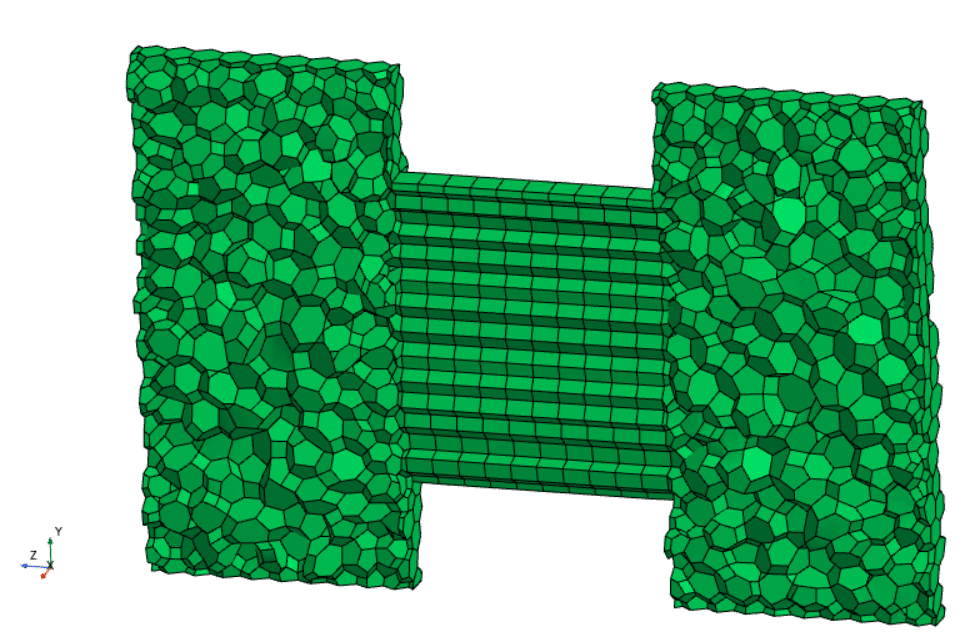
The resulting mesh is shown with a cell surface below, here you can see that the prismatic directed mesh cells (with hexahedral cross-section) match the nodes of the polyhedral cells in the thicker cylinders.

Example with extruder meshing
It is also possible to use the periodic contacts when using an extruder meshing between the thicker cylinders, but then there should be no part/volume at the place where extruder mesh should be created. Starting from only the thicker cylinders you
- Create a Surface extruder operation from the surface at the first cylinder, and the only extra input needed is the distance to the surface at the other cylinder.
- Execute the surface extruder operation and notice that a new part is generated (as seen in the picture below), which will correspond to Part 2 in the previous example.

This time when we are creating the contacts we will use
- Create periodic for the flat surfaces in the surface extruder part.
- But for the contacts between the surfaces at the thicker cylinder we will use Create weak in-place contact, since the extruder mesher will then decide the mesh resolution.
See picture below for how to create the contacts and note also the naming convention at the surfaces due to the surfaces being inherited in the surface extruder, but the surface names are of course possible to change.

In the periodic contact we need to use the settings
- Enable – Mesh only contact and Periodicity – Translational, this is to only get the periodicity only for meshing and not for the flow since we still want the interfaces between the parts to be internal interfaces with in-place topology.

Now we need to
- Create an Automated mesh operation for the two thicker cylinders with the wanted mesh resolution.
- Execute the operation.
- Create a Volume extruder, connected to the surface extruder.
- Execute the operation.
In the picture below you see the resulting mesh where the extruded mesh is using hexahedral prism elements, with conformal interfaces, as in the previous example.

Note: that when using the extruder approach, you can decide the distribution of the mesh cells in the extruded volume. In the picture above a two-sided hyberbolic function is used to have finer cells close to the interface and larger cells in the middle between the interfaces.
Summary
So, why did we go through all this trouble to get conformal meshes and interfaces? As mentioned in the beginning of the blog post the numerical errors are minimized if boundaries/interface have node matching cells. For several applications this level of accuracy is required to be able to capture all the underlying physics. If you for example are simulating heat transfer, natural convection or electromagnetics, the best practice includes using conformal meshing (a non-conformal mesh can predict flow accurately as well, especially in other types of simulations, but to ensure minimized errors a conformal mesh is to be preferred).
We at Volupe hope that this blog post has given you clarity on conformal meshing and that it will help you in your everyday work as a CFD engineer. If you have any questions you are always welcome to reach out to us at support@volupe.com, wishing you a nice weekend!
Author
Christoffer Johansson, M.Sc.
support@volupe.com
+46764479945