This week we will look at the directed mesher in Simcenter STAR-CCM+. We will see how to use the directed mesher in a case where we have a narrow passage in a rotational geometry. In a situation like that, your meshing process can both be simplified, and your cell count greatly reduced by using the directed mesher. The ability to sweep your mesh from one surface to another gives you the possibility of elongating cells along the sweep, instead of maintaining the same resolution as is required in the direction of the flow.
Example geometry in STAR-CCM+
In this test case we have a cylinder with a rather sharp expansion. There is a cylindrical obstacle in our flow domain, forcing flow in a narrow passage over the sides of this obstacle. After the obstacle, the flow is again choked down to the same area as before the obstacle. While the radius if our outer domain is 0.11 m, the radius of the obstacle is 0.109 m, leaving the slit to be only 1 mm thin. This is where we can really utilize the directed mesher. Note that in the example, flow enters from the left side and exits the domain at the end of the longer pipe to the right.

Assume that the inlet flow in this example is uniform and does not vary with angle. Since our geometry exhibits full rotational symmetry, it would therefore be wasteful not making use of this symmetry. Via the execution of several Boolean operations in our case, we end up with a section that is 1/16 of the original geometry. Note that it is important that our two symmetry planes (the one seen in blue in the picture together with the corresponding one on the other side) are named differently. Because aside from being symmetry planes in the simulations, one will also act as the source for the directed meshing and the other one will act as the target (the surface on which the mesh is projected).

What is the directed mesher?
Directed meshing is a method for generating high quality swept meshes in Simcenter STAR-CCM+. The method sweeps a mesh from a surface toward a target surface, through its volume. There is no limitation of where the directed mesher can be used, you can use it with all tools in Simcenter STAR-CCM+, meaning that using the directed mesher will not limit your selection for simulation physics. Directed meshing is beneficial to use in cases where you want to provide a structured mesh in axial direction (as in the picture below). Allowing the meshes to be flow-aligned can result in better accuracy within the solvers. Also note the possibility of stretching the cells at the source or target. In the mesh shown below the axial size of the cells near the source to the left is small and increases as you go further from the inlet. In this example the directed mesher acts similar to the volume extruder mesh operation.

Using the directed mesher
In the example case we will make use of the rotational symmetry, and not sweep along the flow direction. Rather along the symmetrical direction (rotational symmetry) of the geometry. To create a directed mesh, you right-click on the operations folder, the same way you would do with a regular mesh operation. The Directed mesh operation can then be found under mesh. Having selected the directed mesh operation, you will be given the option of selecting what part to apply the operation on. In our example case we will use the 1/16 part.

After having selected which volume to use the directed mesher on, you select which surface is the source surface and which surface is the target surface. In our case we will use the two symmetry planes as both source and target surface. The one named “start” in it will be source and the one named “end” in it will be the target. See clarification in the figure below. On the start surface there is basically a 2D-mesh is created and swept over the volume to “hit” the target volume on the other side.

Under connected part is clarified which volume you are working with. The actual mesh types are selected for the source mesh. The type of meshers you can select is clarified in the picture below. For the volume mesher you can select Polygonal mesher, Quadrilateral mesher or Triangular mesher. The prism layer mesher can be selected for any of these meshers.

For the Auto mesh operation on the source mesh you can use custom controls for volumes or surfaces. In this example, there is a volumetric control for a couple of boxes where the acceleration of the flow becomes the largest. There is also a surface control on the surfaces in the narrow passage.
Under the Directed mesh operation there is an option for “Rotational sweep coarsening”. We will utilize this option, as it allows us to half the cells in our radial mesh progression. Meaning that further most from our axis of rotation there will be a maximum number of volume cells along the actual rotation. As we progress back towards the center of our initial domain we will at certain locations, specified by control, half the number of swept cells. Once this option is ticked in, the mesh coarsening transitions can be created. Note also that the Volume distribution over our region is set to 32, meaning that at the most we will have 32 volume cells across the volume. This will however be reduced by the transition coarsening we have set as we go toward the center of our initial domain. From the below picture you can see that beginning with 32 cells, we have four transitions, all using a merge ratio of 2 (splitting once), we will then go from 32 -> 16 -> 8 -> 4 -> 2 cells.
![]()
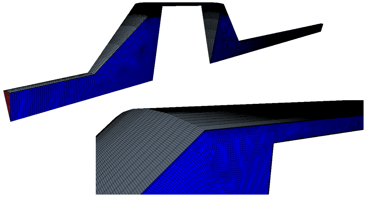
These are the main settings of interest for a mesh like this. The result can be seen in the picture below. We have effectively been able to reduce the number of cells for a case like this, both by utilizing the geometry’s inherent rotational symmetry and by sweeping along the geometry’s rotational axis, allowing for an elongation of cells.
I hope this has been useful for you, and as usual, do not hesitate to reach out if you have any question regarding this or anything else regarding Simcenter STAR-CCM+. The place to reach out to is support@volupe.com.
Read also:
How to run a basic simulation in Simcenter FloEFD
Finding zones that potentially give poor volume mesh
Simcenter STAR-CCM+ version 2020.3 news – Part 2
How to run Design Manager Projects
Release update on Simcenter STAR-CCM+ 2020.2 part 1
STAR CCM+ Product page


