In this week’s blog post we are going to look at how to create a parabolic function, which for example can be useful when you want to define a fully developed velocity profile at your inlets.
Velocity profiles
Due to friction, the flow field obtains a lower velocity close to the walls. And since continuity must be fulfilled the flow that goes in must come out as well (if we reach a steady state for the flow field). These two criteria mean that velocity must increase further away from the walls. In the picture below a velocity profile in a pipe is shown, which illustrates that a fully developed velocity profile is created when the flow field has reached a steady state in the pipe flow – meaning that the profile does not change further downstream. This parabolic shape can be approximated easily with a field function, which we will investigate in more detail in the following sections. The image below is from Wikipedia [1].

Additional comment: The velocity profile looks different depending on if the boundary layer is laminar or turbulent. Turbulent boundary layer flow has a more rapid increase in velocity than laminar boundary layer flow. So, the velocity profile needs to be calculated if the problem statement requires the exact profile. But if an approximated profile is good enough for your simulation, the method described in this blog post can be used.
Create a local coordinate system
Since the profile in this example is symmetrical in terms of rotation around the center axis of the pipe, we will first define a local cylindrical coordinate system. How to do this is shown in the picture below.

This coordinate system will be used to define the parabolic function. The radial coordinate will be used in the field function, if the z-axis is defined as in the picture below.

Parabolic field function
Let’s now take a look at the actual field function.
Since the friction at the wall makes the flow velocity go down to zero that the wall, but then the flow is increased exponentially further away from the wall, there is a large velocity gradient close to the wall. This can for example be captured with an exponential function, where the exponential behavior is dependent on a parameter for the exponent. This makes it possible to control how rapid the exponential behavior should be. Name the parameter “Profile_polynom”. The maximum velocity of the profile, which will control the maximum value of the profile, should also be set to a parameter called “Maximum velocity”.
The field function will be built as an expression multiplied with the maximum velocity variable, and then have a function normalized with the maximum radius powered to the profile polynomial. The expression should be built as the maximum radius powered to the profile polynomial and subtract the local coordinate in radial direction powered to the profile polynomial. You then get a field function that looks like the expression below.
${Maximum_velocity}*(pow(0.05, ${Profile_polynom})-pow($${Position}(@CoordinateSystem(“Laboratory.Cylindrical 1”))[0], ${Profile_polynom}))/(pow(0.05, ${Profile_polynom}))
In the picture below you have a preview of the parabolic function going from the maximum velocity in the middle of the pipe (radial coordinate zero) and zero velocity at the largest radial coordinate (in this case 0.1m since the radius of the pipe was 0.1m. Here maximum velocity was set to 10 and profile polynomial to 2.

Additional comment: The maximum value of the radius for the pipe can also be set as a parameter if desired. This value is even possible to extract from a report for a more generic field function.
If you instead want to have a steeper profile, with more rapid increase in velocity, you can for example increase the profile polynomial to 5, as in the picture below.

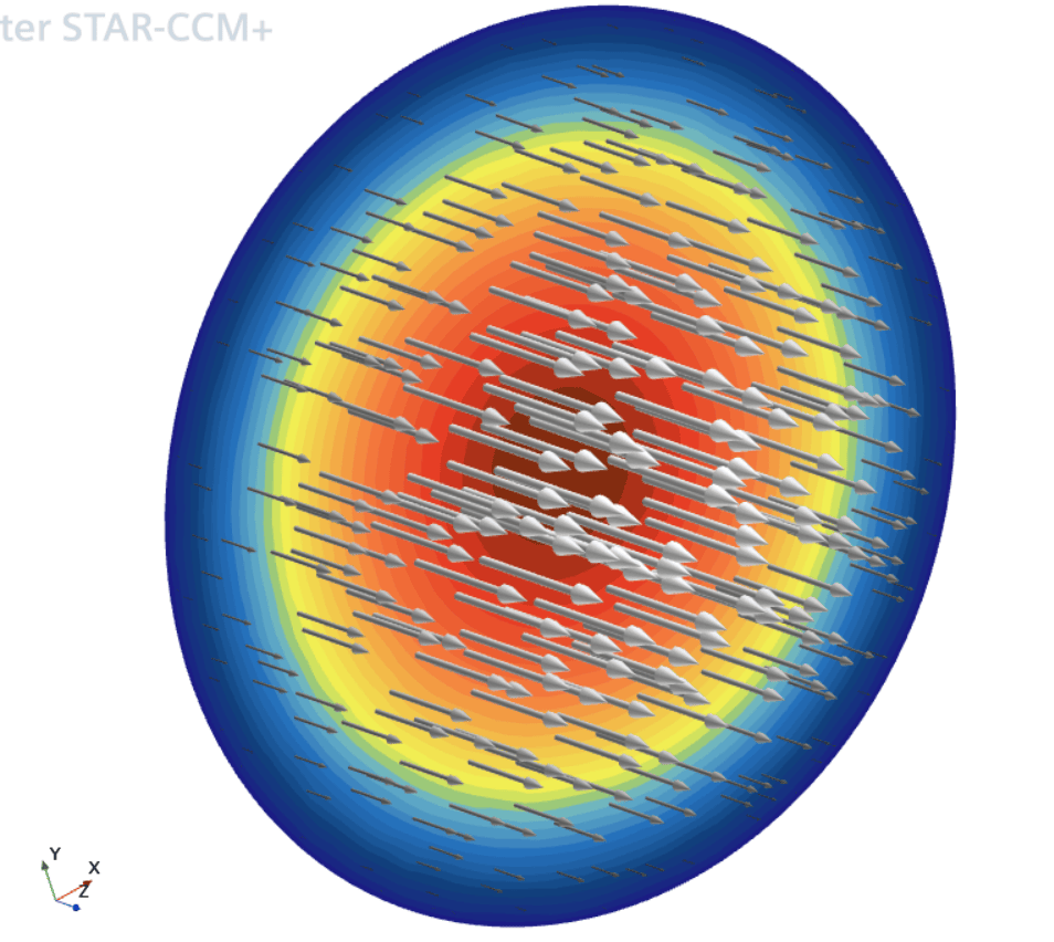
The velocity profile will then result in a flow field like in the picture below.

We at Volupe hope that this blog post has been helpful and that this can make your life easier in your every-day-work as a CFD engineer. If you have any questions you are more than welcome to reach out to us at support@volupe.com.
This post was posted today, on a Thursday, since tomorrow is a national holiday in Sweden, where we celebrate Midsummer. Wishing you all a pleasant long-weekend!
References
[1] Wikipedia – Entrance length (fluid dynamics), January 2023, https://en.wikipedia.org/wiki/Entrance_length_(fluid_dynamics).
Author

Christoffer Johansson, M.Sc.
support@volupe.com
+46764479945


