In this week’s blog post we will look into how to create a spread flow field at the inlet. This can be useful when you want to model a spread flow, without resolving the geometry that is causing the spread. It should be noted that it is always interesting to first run a simulation where the geometry causing the spread is included, to verify the spread angle. Verification can of course be done based on empirical studies as well.
The setup we are aiming for in this blog post is an inlet with circular surface with velocity magnitude that is uniform, and a spread angle of 15 degrees leaning from boundary normal direction towards radial direction. This means the flow will be perpendicular to the surface in the middle and the flow angle will increase linearly to 15 degrees in radial diretion outwards at the edges of the surface. We will present two ways on how to set up this velocity inlet boundary condition, via a field function and manipulating the inlet boundary to a rounded surface.
Download simulation files which correspond to the simulation in this blog post.:
[wpdm_package id=’5507′]
Spread flow via a field function
Using a field function to create a spread flow is quite convenient, especially if you have multiple boundaries to apply the boundary condition on. To be able to use the same field function regardless which boundary you apply the boundary condition on you must create a local coordinate system, with origin in the center of the boundary. The coordinate system should be of type cylindrical and have the radial and tangential directions in the plane of the boundary, and the axial direction (z-direction) as the boundary normal. On the inlet boundary the “velocity specification” under “physical conditions” should be set to “components”. For the velocity the field function describing the spread should be used and the local coordinate system should be specified, as seen in the picture below.

When it comes to defining the actual field function it will consist of a multiplication factor and three components, where the components are divided by commas inside a bracket:
1*[sin(0.0174533*15*(1/0.01)*$$Position(@CoordinateSystem(“Laboratory.Cylindrical 1”))[0]),0,cos(0.0174533*15*(1/0.01)*$$Position(@CoordinateSystem(“Laboratory.Cylindrical 1”))[0])]
The multiplication factor, before the bracket, is set to 1 in this example and is multiplying all components. If you would like to have a flow of 20m/s instead of 1m/s you can change the multiplication factor to 20 instead of 1. Then we have velocity component in radial direction (first component), which is using the trigonometric funtion sine. The component in tangential direction (second component) is set to zero here, but if swirl is wanted here is where to define the swirl. The component in axial direction (third component) is using the trigonometric function cosine.
Inside the trigonometric functions there are some scaling factors:
- 0.0174533 is converting degrees to radians (1 degree is 0.0174533 radians).
- 15 is the value for the spread angle.
- (1/0.01) defines how large your inlet is, where you should swap 0.01 for your radius. The value should be using meter as dimention.
- The last term is using the radial position in the local coordinate system to create a lower lean angle in the middle and a higher lean angle further out from the center. Note that both the first and third component in the field function is using the radial position, indicated by “[0]” after the position variable. The syntax numbering is starting at “[0]” for the first component, using “[1]” for the tangential component and “[2]” for the third component of the axises.
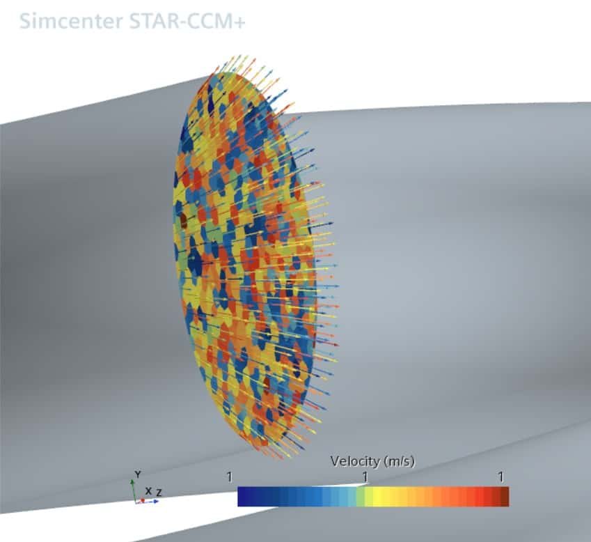
The resulting flow field from the field function is shown in the picture below, where the colour indicates that all arrows have the same velocity (please note that the colour bar goes from 1 to 1).
Spread flow via a rounded inlet boundary
If you rather want to specify the spread via manipulating the shape of the inlet boundary, you can follow the steps:
- Create a block and a sphere.
- Subtract the block from the sphere, meaning that the sphere is the “target part”.
- Unite the pipe and the resulting part of the sphere at the position where the inlet should start.
It can be a little bit tricky to define the radius and center of the sphere, so for this my colleague Robin created a very nice illustration, see picture below. Where the “1 le” is corresponding to your inlet diameter, “x” is the distance between the inlet location and the center of the sphere, and “y” is the radius of the sphere.

On regional level the curved boundary should have boundary conditions “magnitude+direction” for “velocity specification” under “physical conditions”, and the direction should be boundary normal. In the picture below you will see how an inlet like this can look like. Note that this method will increase the surface area of the inlet, which can give a larger mass flow – a normalization for this may be needed depending on the application (it is possible to measure the surface area with a report in Simcenter STAR-CCM+).

We at Volupe hopes that this blog post has been helpful, and if you have any questions you can always reach us at support@volupe.com.
Related to this blog post I have also created a discussion at the PLM community (IdeaStorm). If you would like to have the spread angle as an option complementing the already existing options, you can vote (like the discussion at the community) for the idea via this link: https://community.sw.siemens.com/s/question/0D54O000079u07LSAQ/i-would-really-like-to-have-the-possibility-to-define-a-spread-angle-for-inlet-flow-on-the-inlet-boundary-in-simcenter-starccm-is-this-something-you-also-hope-that-siemens-can-add-as-a-feature.
Author
Christoffer Johansson, M.Sc.
support@volupe.com
+46764479945