FloEFD Introduction and purpose
This week, I will show you a simulation from the software Simcenter FloEFD. This blog post will be a tutorial of how to set up and run a simulation in Simcenter FloEFD. Simcenter FloEFD is a CFD-tool to simulate mainly flow and heat transfer, just like Simcenter STAR-CCM+, but the software is a frontloading CFD-tool created for design engineers without experience of CFD simulations. Simcenter FloEFD is available as a stand alone version, but it can also be used as a plug-in to a CAD-program. In the plug-in version you can easily change between editing the geometry in CAD and get quick feedback about how the geometry performs regarding to the flow and/or the heat transfer.
Simcenter FloEFD is a powerful and quick way of getting simulation results. The amount of settings needed to be defined are minimized to make it possible for a CAD engineer to evaluate the geometry before handing it over to the CFD engineer. By defining the physical problem, a goal which determines if the simulation is complete and setting rough mesh settings, the solution to the simulation is only one click away.
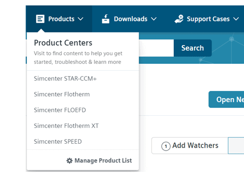
When importing the geometry into Simcenter FloEFD, you will get a window, like the picture below. In the GUI you will see the geometry and to the left there is a tree-structure (similar to the one in Simcenter STAR-CCM+) where you will be able to choose which settings to modify. Above the geometry there is a toolbar to perform actions. In this weeks blog post I will show you a simulation of flow within a bent pipe.

When starting to analyze the internal flow in a pipe, it can be good to create a cross-sectional view. In this way we can see the inside of the pipe. Click on Hide all types -> View planes, inside of the geometry display. The right-click on the pre-defined plane you want to use for the cross-sectional view and select Section view. See the picture below for instructions.

Extracting fluid volume
You will now see a cross-section of the pipe. Zooming in to the edge of the pipe we will see something called a Lid. The lid is used to make the geometry sealed. I have created this lid in Siemens NX (together with the geometry). There is a tool in Simcenter FloEFD for creating lids, but I recommend you to create your own with your CAD-program. If you would like to use the integrated way of creating lids you will find it under Tools and then Create lids. Creating lids with this feature works best on holes with flat surfaces. As you can see, in my simulation, the lid is overlapping the pipe bend. This is made on purpose in Siemens NX, since it is not recommended to have surfaces sharing the same location.

The lid is used to create a closed fluid domain. When the domain is closed, we can set a Wizard for the simulation settings. In the toolbar, the wizard is located in the upper left, just below the menus. In the wizard, you set the name of the project, units of the simulation, if the simulation involves internal or external flow (if you have both, choose external), specify fluid, how your walls should interact with the fluid and finally the initial conditions of the simulation. This might seem like a lot of settings, but the menus are clear and the possible choices always have good default values which makes it easier for the engineer to set the settings needed for the simulation.
In the picture below, you see the Computational domain, which is the next setting to set in the toolbar.

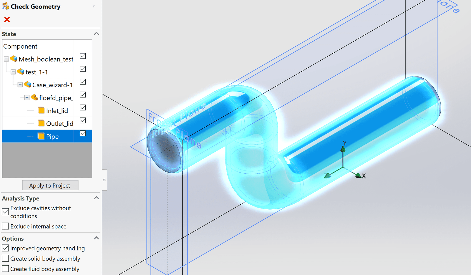
To validate that the computational domain will define the fluid domain in the correct way, you can use the powerful tool Check geometry. There are two checks which are recommended to perform before going to the next step in the setup: Check and Show fluid volume. The Check will give you information about if the geometry is closed, and therefore ready to be used in the simulation. This is done by giving the output OK if the geometry is closed. Show fluid domain will give a graphical output with the fluid domain, see picture below. The volume of the domain will also be displayed in the output window. Note that if you do not get the expected value, for example, if the fluid domain has a volume of 0 cubic meters, you have probably used the function Exclude cavities without flow condition. This is a setting you can use if you have cavities in your geometry which you do not want to run calculations for, but in this specific case all the internal volume will be seen as a cavity, and the simulation will therefore not have any volume to perform the calculation on. This setting for the cavities is available to activate in the wizard, where you set internal or external flow.

Boundary conditions
When you have obtained the desired fluid domain you are ready to set the Boundary conditions for your simulation. Boundary conditions are settings (mostly applied) on surfaces. You should have at least one boundary condition which will not drive the flow, to have a variable to solve for. You should also have at least one boundary condition that will drive the flow, in this simulation a mass flow inlet will be used for the driving boundary condition. The inside of the lid will be the internal surface where the boundary condition will be applied. If you right-click on the lid, you can choose Select other, and there select a surface belonging to the lid even though it is not visible from your view. Hover over the different surfaces and select the one highlighting the desired surface in orange. Choose the boundary condition Environment pressure for the inside surface of the outlet (this corresponds to Pressure outlet in Simcenter STAR-CCM+).

Simcenter FloEFD uses Goals to determine if the simulation is complete, and now it is time to define a Surface goal for the outlet as seen in the picture below. For this simulation I will use an average of the static pressure on the outlet, which has to get stable between the iterations when solving for the flow field. Only then the solver will stop iterating and a converged solution has been obtained.

Mesh
To calculate the flow field, we have to discretize our domain, using a mesh. In the picture below, the basic mesh is shown (right-click on Mesh and Show basic mesh). The settings for the basic mesh is refined to level 5 in this case since the geometry is quite small. It is recommended to use a level of mesh refinement for the basic mesh between 3 and 5. The solver uses wall-functions to determine the flow close to the walls, which makes the need for finer cells by the wall less relevant.

I will still show how to refine the mesh with a Local refinement in the bend, but keep the Refining cells settings to 2 for both the volume and the surface mesh. By setting the number of cells used in the channel to 15, the mesh settings will now be good for this case. Select the inside surfaces of the bend part of the pipe for the mesh refinement. A note here is that this surface refinement will only affect the solid in this case, since the surface is part of the solid and the solid/fliud interface.

Solving for the flow field
All settings for the simulation are defined, and the solver is now ready to run, by clicking Run in the toolbar. The solver will first mesh the fluid domain and after that, the solution of the flow field is iterated and when the goals of the simulation are achieved the solver will stop. The solver uses a pop-up window and here you can monitor the goal, control the solver and also create plots for visualization meanwhile the solver is running.

Post-processing
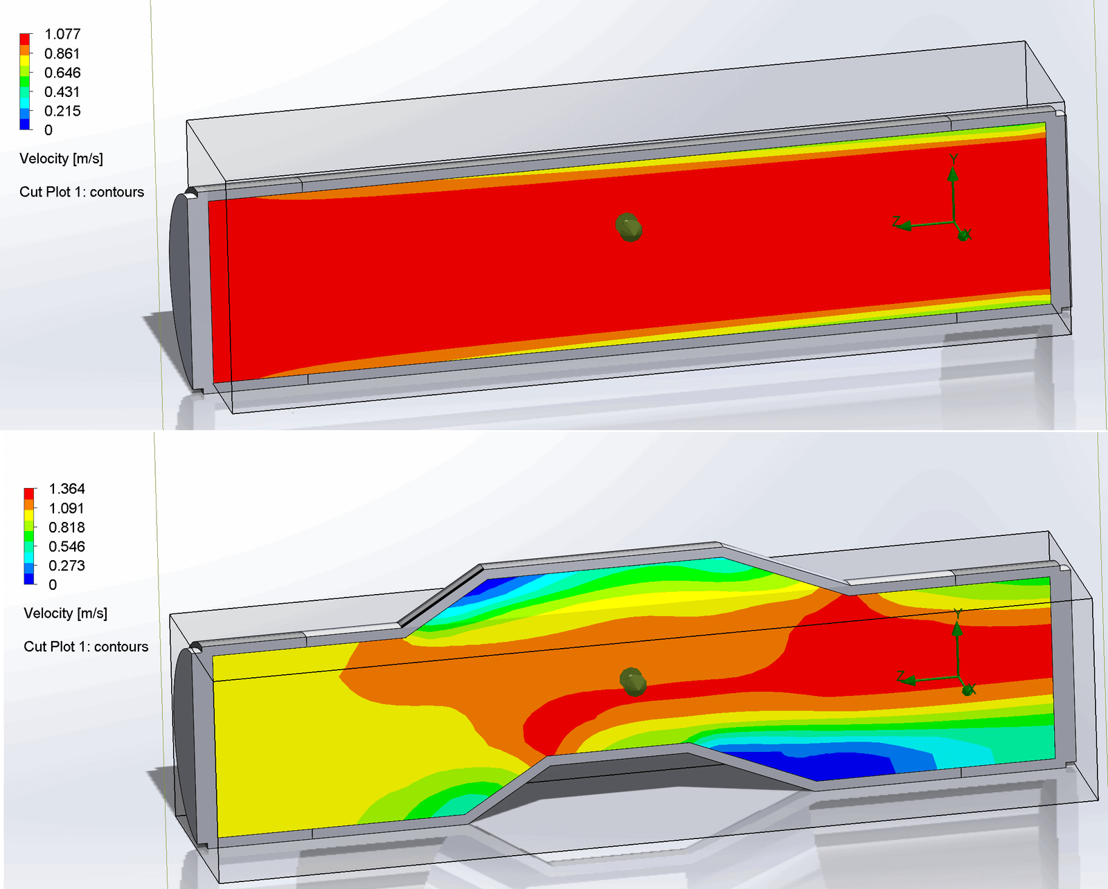
When the simulation is obtained, post-processing is the next step forward. Note that the post-processing is of course possible to set up before running the solver, like in Simcenter STAR-CCM+, in this case I will follow the work flow from top to bottom in the tree-structure though. In the picture below a visualization of the velocity field is displayed as a Cut-plot (contour plot) on the pre-defined plane used for the cross-section.

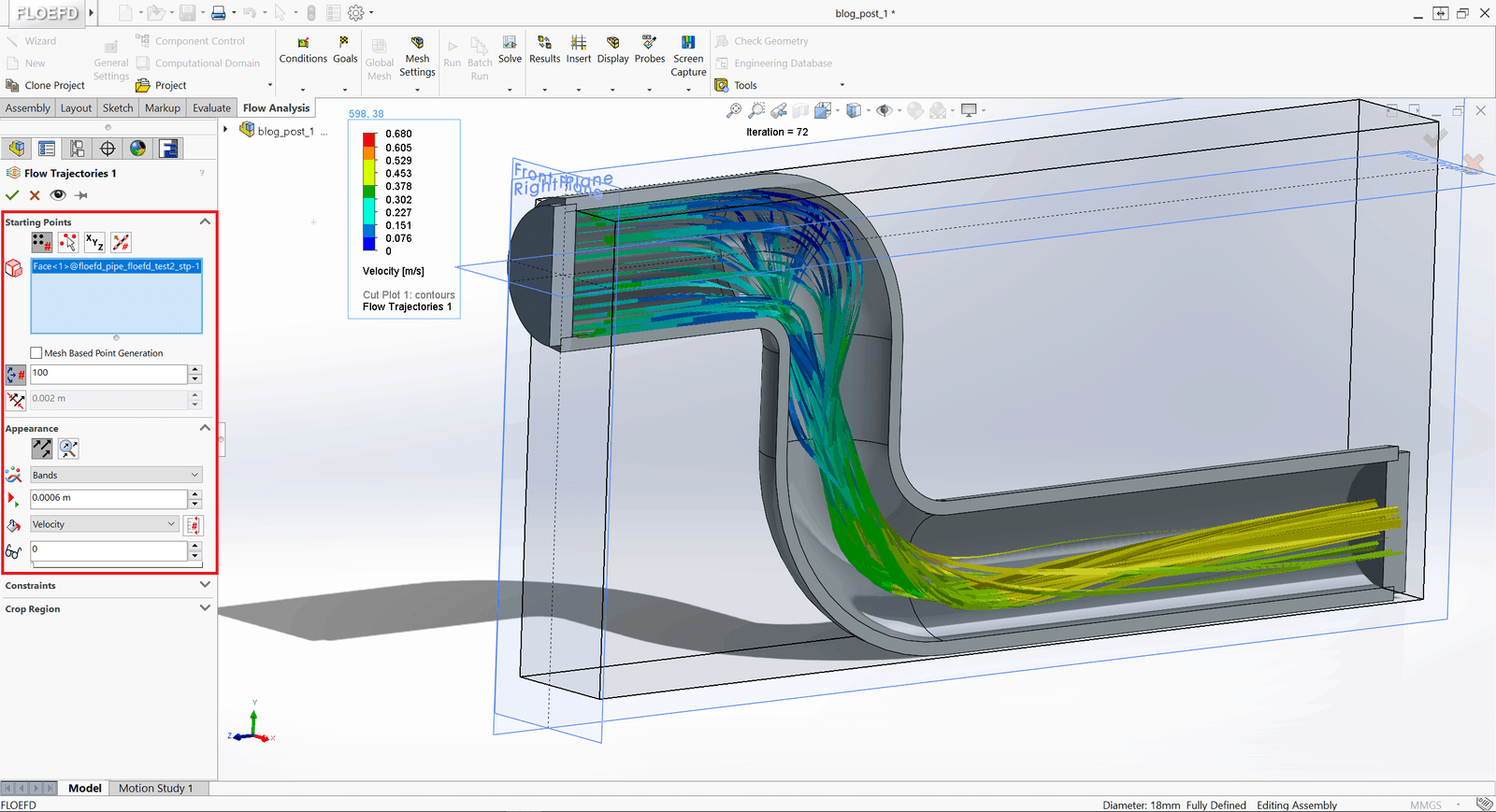
There are many different ways to visualize the flow in Simcenter FloEFD. The picture below shows another way of visualizing the flow in the domain – Streamlines (type of streamline is Band in this simulation).
I hope this week’s blog post about the software Simcenter FloEFD has been interesting to read. Simcenter FloEFD is just on of the software Volupe is supporting besides Simcenter STAR-CCM+. Feel free to contact us at support@volupe.com if you have any questions about Simcenter FloEFD or any other questions regarding your simulations.
Read also:
How to set up the wizard in Simcenter FloEFD
Directed meshing in Simcenter STAR-CCM+
How to set up a CHT simulation using simulation operations
Finding zones that potentially give poor volume mesh