Many marine engineers might share the pain: You have a floating object in a transient simulation and wanting to test different trim/Center of Gravity (CoG) configurations (e.g. in a design study or submarine ballast tank blowing). But you would like to start from a previous converged solution without the need to start from a once more initialized simulation.
However, the need for dynamically changing CoG can also be found outside the marine world, for instance for rocket fuel burning simulation. Theoretically, you could do this with external forces/moment to replicate the CoG shift. However, it’s not the most elegant solution.
For now, the best way to accomplish this is to map all the data, clear solution and restart from the last solution. You basically run the simulation, then when you want to start from these conditions again, you use the volume data mapper to store the current state. Then transform the base part by moving it to the current position, based on the solution. Re-mesh, initialize with a now CoG and run again.
A sudden change might, however, yield instability of the solver. It is thus recommended to gradually change the CoG. This should be automated with Simulation Operations. In the following sections we describe the required steps exemplified an boat with moving ballast in longitudin al direction. The initial simulation is already performed and the DFBI motion converged to an equilibrium floating condition.

Step 1 Parametrize
First of all, we need parameters for the CoG coordinates that needs to be changed and assign them to the Center of Mass properties at the DFBI Body.

But additionally, since our simulation has 2 DOFs (heave and pitch), we need 2 additional parameters to store and relate orientation to the initial position, which will be lost otherwise. The heave and pitch relative to initial position at t = 0, which will also be used to transform the base part to the latest position.
![]()
Step 2 Transform
A Transform operation is placed before the mesh operation. It contains translation for the heave and rotation for the pitch. Here we rotated the base part around latest CoG. Meaning that we will need an extra coordinate system for the simulation operation setup. The Mesh operation needs to be performed after the initialization from Mapped Data. At that point, CoG has already been updated. Thus, we need extra parameter CoGx-1 and CoGz-1 to place the origin for rotation correctly.

Step 3 Mapp data
Run the Data Mapping of the solution for all data needed at initialization: Turbulence, pressure and volume fraction scalar fields, and the velocity vector field. Once the data are stored in the Volume Data Mapper you can clear the solution.

Step 4 Initialize with Mapped Data and solve
Change the initial condition of the continuum to Mapped Data and initialize with the new coordinates of CoG and the saved fields. After initialization re-mesh and solve.


Simulation Operation

Since these steps are a highly repetitive task, it is recommended to leave that to the simulation operations. As provided below, we loop over the steps outlined above. The CoGx value is continuously increase by constant delta. To keep the Data Mapper field function clean, and to avoid data artefacts to mess with the update, we throw in a Clear Mapped Fields at the end of a loop. This is technically no Simulation Operation but a java function. Consequently, the whole automated run is started by a java macro which calls the
sim.get(DataMapperManager.class).clearMappedFields();
When the simulation operation block named “Clear Mapped Fields” is active. If you like to know more about how to combine java macros with simulation operation, please visit our dedicated blog post https://volupe.se/automation-of-marine-propeller-simulation/
Is it worth it?

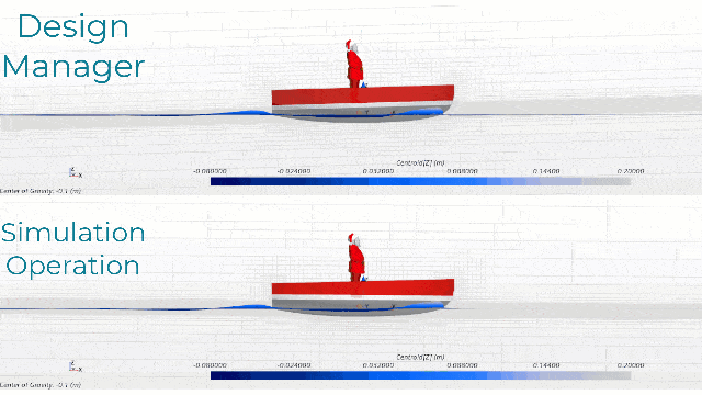
Different configurations of a varying parameter can easily be set up with the help of Simcenter STAR-CCM+´s Design Manager tool. So, is the outlined procedure superior? A design sweep would be the choice for this task with the Design Manager. But the Design Manager would need to start with an empty solution to initialize with new CoG coordinates. By mapping solution data of with previously converged flow field has advantages in a speed up to obtain converged solutions. The quality of the solution can also be expected to improve due to the transformation of the base part, where the mesh is realigned with the free-surface.

Let´s compare a sweep of 7 different longitudinal coordinate for CoG, run from the Design Manager and with Simulation Operation as proposed above. The test case is simple and the stopping criteria is either maximum physical time of 20s or an asymptotic limit of the trim monitor. With this setup, three out of seven cases converged with the mapped solution significantly faster than the initialized solution, as in the example below for a CoG = -0.05 m. This speed up resulted in a faster lead time of the whole range of CoG simulation. Taking into account that most DFBI simulation run for a longer physical time and contain more appropriate the advantages of initializing with mapped fields is something to consider when running future simulations.

We at Volupe hope that this blog post about automating boring manual task has been interesting and that it will help you in your work. You can download the simulation file and java script described here below. And don’t forget that you are always welcome to reach out to us at support@volupe.com.
[wpdm_package id=’6109′]
The Author
Florian Vesting, PhD
Contact: support@volupe.com
+46 768 51 23 46


