Download the simulation files which correspond to the comparison for interfaces in the end of this blog post:
[wpdm_package id=’6925′]
In this week’s blog post we will look at interfaces and how to create interfaces in Simcenter STAR-CCM+. The reason behind why we need interfaces is to connect different parts, so the simulation understands that the fluid regions are connected and not separated only because two different geometry parts are used. Note that even though the parts are sharing location in space for one surface (or several), interfaces are needed to specify that the fluid regions should be connected.
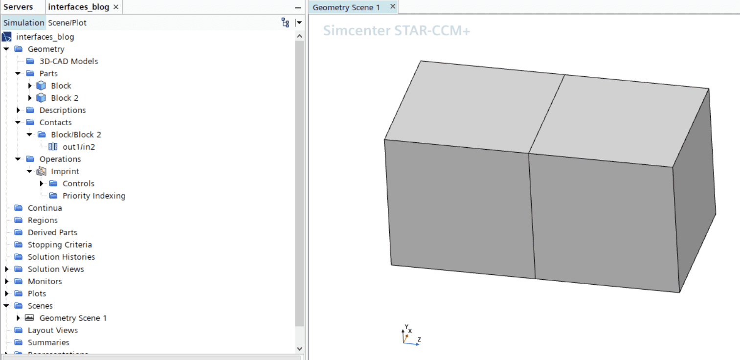
In this blog post we will look at two blocks, like in the picture below, to explain interfaces and how to set them up. In the picture you can see that a contact between the two blocks is created via an imprint operation. Creating contacts will make sure that interfaces are created automatically (if you want them to), and correctly, when assigning parts to regions – hence the recommendation to use this workflow.
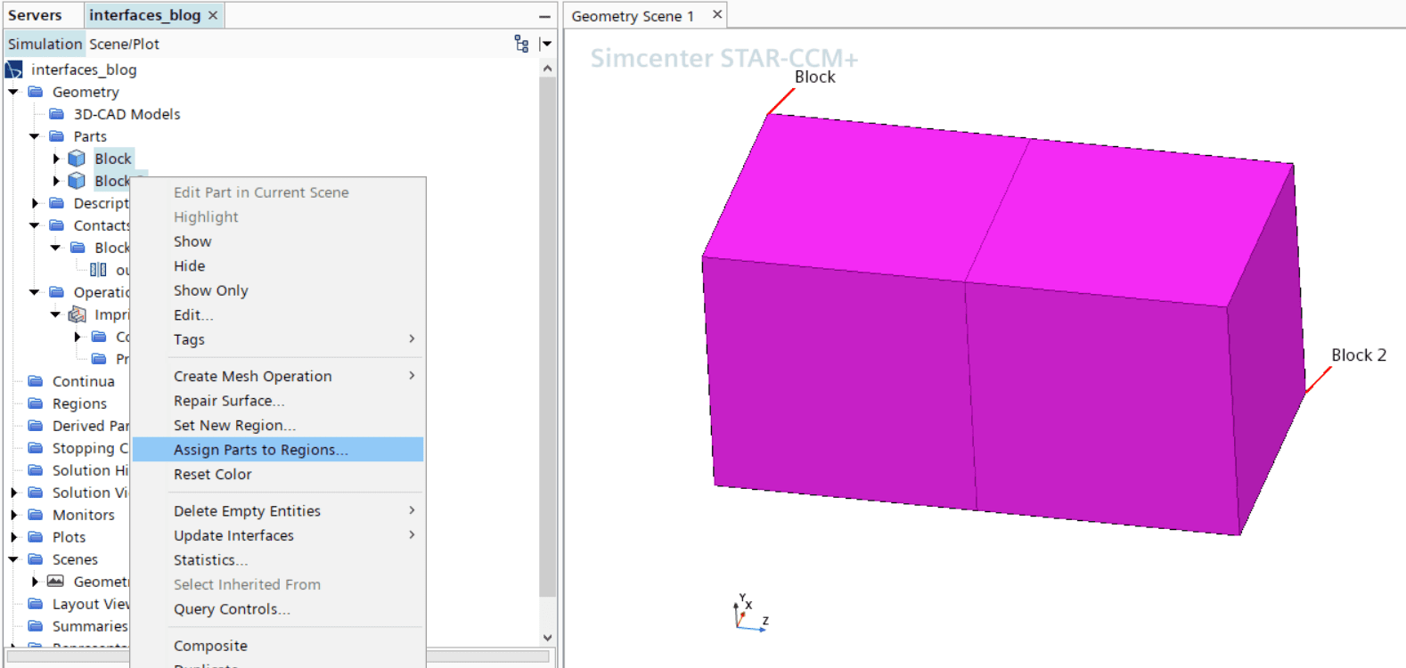
When assigning parts to regions, ctrl-select the parts which should be connected to the regions, as in the picture below.
When assigning the parts to regions you select which parts are wanted, along with changing the settings to create regions & boundaries & feature curves for EACH part & surface & curve. Otherwise, you will not keep the split of your geometries which you have already created. See picture below where to change the settings. In this pop-up menu you also have the possibility to select how you want your interfaces to be created. 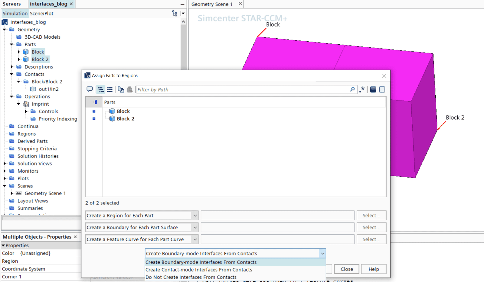
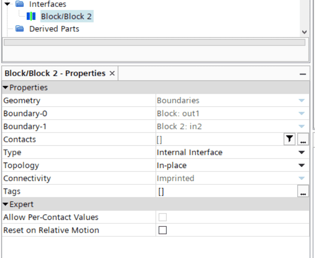
The first of the three choices on how to create interfaces are boundary-mode from contacts. Here you will relate boundary-0 and boundary-1 of the interface to the inlet and outlet surface of the interface, as seen in the picture below. The Boundary-mode interfaces can create an interface between one, and only one, pair of boundaries. If you need to have the same split of interfaces as you have for the boundaries this setting is recommended.
If you instead use the contact-mode from contacts option, you will relate the contact to the interface. Both these options to create interfaces will create the interfaces automatically. The contact-mode boundaries can create an interface out of any number of pairs of boundaries. If number of interfaces should be minimized and there is no need for interfaces to be split per boundary, this setting is recommended. 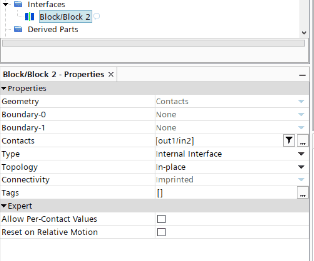
If you instead choose to not create contacts when assigning parts to regions (third option), you can create interfaces manually as in the picture below. By ctrl-selecting the regions of interest you can create interfaces by right-clicking on the regions and select to create interfaces from contact-mode boundary interface. This way of creating interfaces at region or boundary level is especially useful when using overset mesh, see link for our blog post about overset meshes here https://volupe.se/overset-mesh-in-simcenter-star-ccm/. 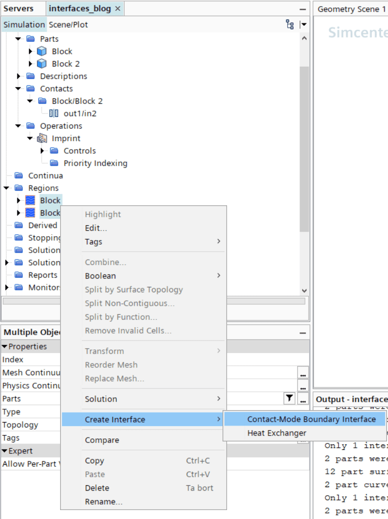
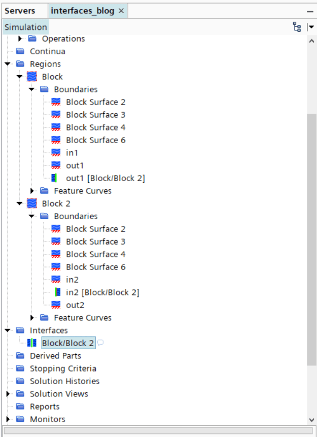
When interfaces are created you will get an interface boundary automatically created, that will overwrite the boundary condition for that boundary with its settings. For example, in the picture below for Block, the boundary “out1” (which is connected to boundary “in2” at Block 2) will not be a wall – instead it will be an internal interface as stated in the interface properties.
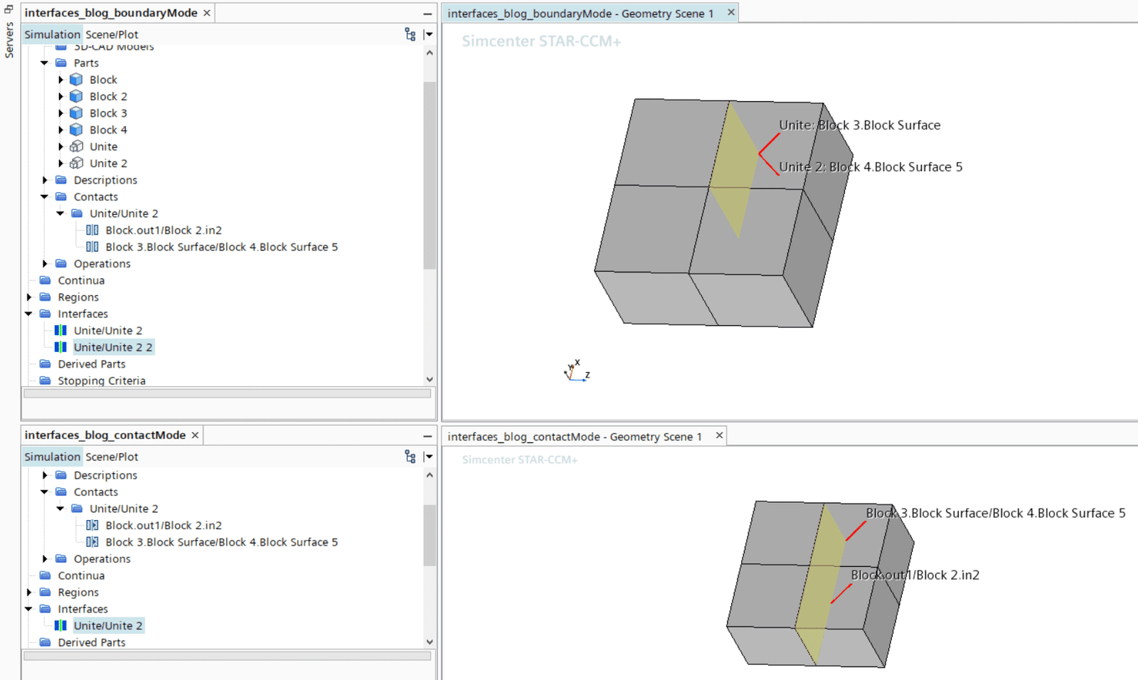
Comparison between boundary mode and contact mode for interfaces
To visualize the difference between boundary mode and contact mode interfaces I created two more simulations where the geometry is built out of four cubes instead of two, see picture below. In the simulation using boundary mode interfaces there is one interface created per pair of contacts (one of the two interfaces is highlighted in the picture), and for the simulation using contact mode interfaces only one larger interface is created. For looking at the set up more in detail the simulation files are attached via the link in the top of the blog post.

We at Volupe hope that this blog post has been informative, and that the workflow for creating interfaces has become clearer. If you have any questions you are always welcome to send them in to support@volupe.com.
Author
Christoffer Johansson, M.Sc.
support@volupe.com
+46764479945