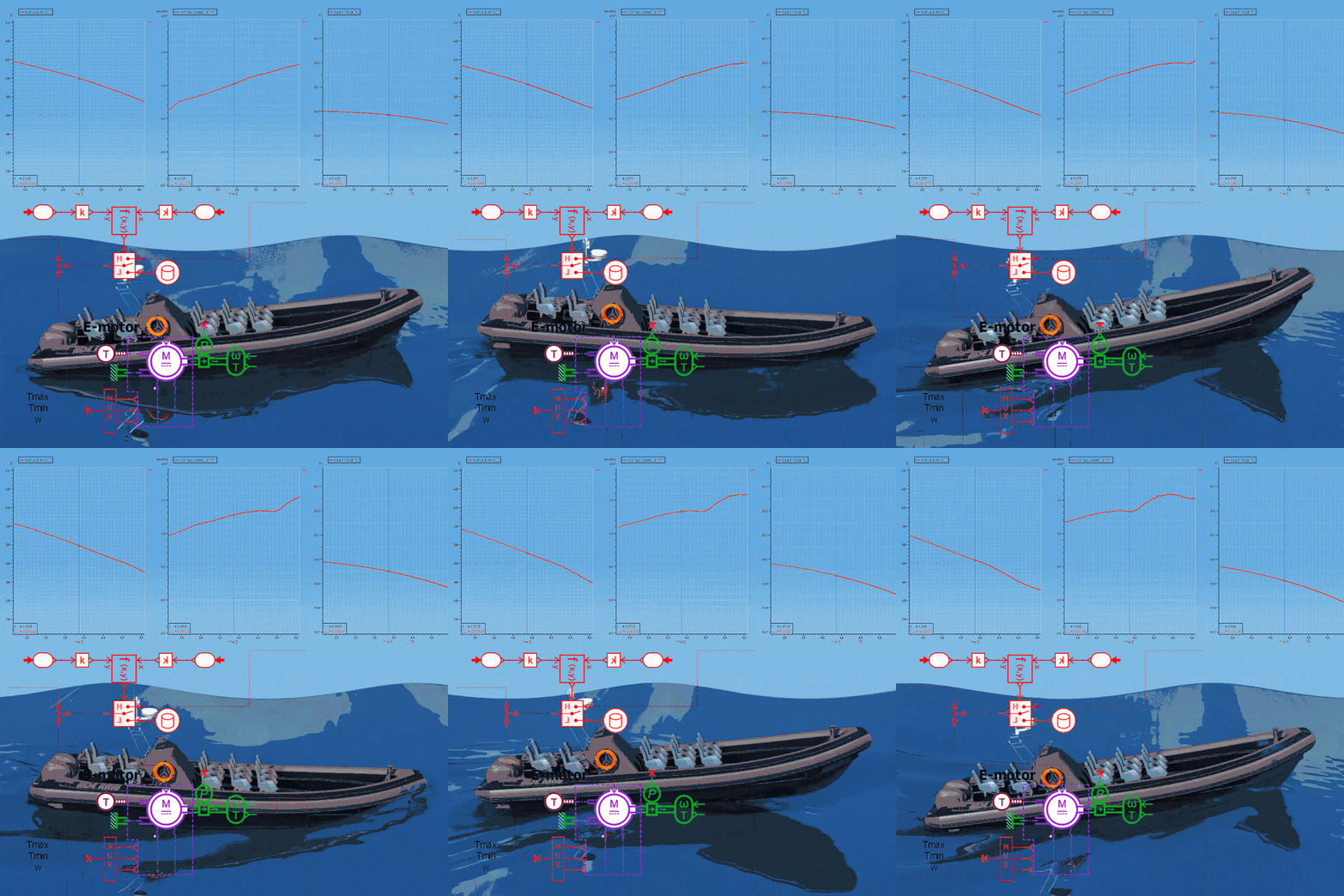
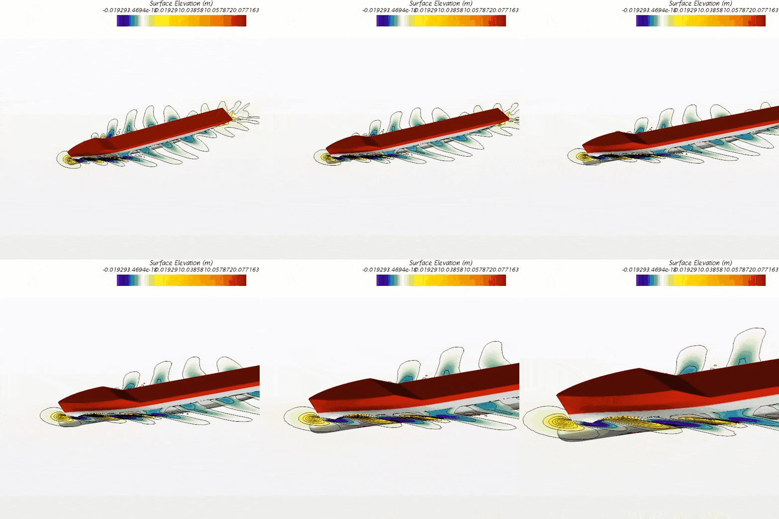
In this week’s post we will go through an interesting simulation case carried out by coupling Simcenter STAR-CCM+ together with Simcenter Amesim. In this marine scenario, Simcenter STAR-CCM+ provides the detailed dynamics of a Rigid Inflatable Boat (RIB) moving through rough sea, whereas system simulation provides the boat’s electric propulsion and control system. Additionally, an overview of how to set up co-simulation between Simcenter STAR-CCM+ and Simcenter Amesim by employing Functional Mock-up Units (FMUs) will be provided.
Combining the strengths of the two software offer many benefits. Accounting for instantaneous forces from waves hitting the hull at high speed is a difficult fluid dynamics topic and typically not something managed with system simulation. Vice versa, constructing a detailed electric propulsion system along with its control is very cumbersome to address using only scripting in Simcenter STAR-CCM+.

To connect Simcenter STAR-CCM+ to Simcenter Amesim two main Co-Simulation paths are avaiable to the user:
- Simcenter Amesim Co-Simulation using the built in two-way Simcenter Amesim connection. Here communication is established using TCP/IP where for example Simcenter Amesim could be configures as the server and Simcenter STAR-CCM+ the client. More information concerning this approach together with another co-simulation example can be found by following this link.
- Co-Simulation using the Functional Mock-up Interface. A framework and software-independent standard for exchanging dynamic simulation models which specifies how to couple simulation models built with various simulation tools.
Following the FMI standard, models called Functional Mock-up Units (FMUs) are created. These typically represent a dynamic network capable of running transient simulations. Simcenter STAR-CCM+ is able to import co-simulation type FMUs based on version 1.0 or 2.0 of the FMI standard and the generated FMU should be based on a 64-bit architecture. Model Exchange types of FMUs are currently not supported.
The final FMU is essentially a compressed folder with the extension .fmu comprising of a collection of files, such as the model definition (.xml), any required solvers (or the means of communicating with the external software) used to run the model defined in the FMU, or additional tables/data used by the model. In some situations, such as in a simplified control system, an external software tool might not actually be required for the computation of the FMU and no additional solver apart from the one inside Simcenter STAR-CCM+ is used.
The FMU also specifies which variables to exchange between Simcenter STAR-CCM+ and Simcenter Amesim and accounts for the exchange of scalar values. The FMI standard does not allow spatially varying quantities such as scalar fields to be exchanged.

FMI interfaces provided in Simcenter Amesim
Within Simcenter Amesim a FMU Export Assistant is available to aid in the process of generating the FMU. Once a system model is built, an interface block is added to the model sketch and the FMU interface is selected.

The FMU Export Assistant is accessed from the Simulation mode under the Interfaces menu, and the assistant:
- Prepares the model for export by generating the FMI API functions.
- Compiles the C source code of the model into binary files compatible with the selected target environment.
- generates the XML model description file.
- Compresses the files, i.e. the description file, binaries, into an FMU file.

Inside Simcenter STAR-CCM+ two Physics continua are involved when coupling to an FMU. One internal for the Simcenter STAR-CCM+ model, and one external for the FMU.
To set up a co-simulation with an FMU, the co-simulation and FMI model options are added to the internal Physics continuum and the internal continuum is assigned to the appropriate region. For the external model, a new physics continuum needs to be created containing the models External Continuum, FMI, as well as a selection for the time model. The newly created FMU physics continuum also requires a region to represent the FMU inside Simcenter STAR-CCM+.

When the External Continuum model is added, a new link is created under the External Links node. In this link settings for the co-simulation are specified in addition to which scalar values to exchange.

Two approaches for exchanging input and output variables with the FMU are available:
- Co-simulation zones specify a set of Simcenter STAR-CCM+ model parts (boundaries or regions) that exchange data with the FMU. Values that are imported from the FMU through a co-simulation zone are stored as spatially-uniform fields that can be used to set boundary and region settings.
- Link value specifications are generally useful for exchanging general data that are not necessarily applied to the boundaries or regions. Values that are imported from the FMU through link specifications are stored as single values.
Finally, the FMU file is added by navigating to File –> Import –> Import User Library. The imported FMU is placed under a new node called User Library and after this step the FMU has to be connected to the External Link by selecting it in the FMI Resource Reference as shown below.

Now, let’s acquaint ourselves a bit more with the marine co-simulation case.
The interaction between Simcenter Amesim and Simcenter STAR-CCM+ is done using the three main variables: 1) Velocity, which is compared against a desired velocity curve and used to control the electrical motors output torque. 2) Torque, input to the virtual disk propeller model inside Simcenter STAR-CCM+. 3) Propeller RPM used as feedback to electrical motors.
In this simple study an electric Rigid Inflatable Boat (RIB) is accelerating through heavy waves and because of a poorly dimensioned battery cooling system on my part, the boat runs into trouble. As the electric motors draw power to propel the boat forward the battery overheats and reaches a temperature above 38 [°C]. This in turn triggers the control system to abruptly turn off the motors, leaving the boat dead in the water.
In the animation below the boat movement is shown along with a velocity plot (bottom left) and plot containing propeller rotational speed and the internal temperature of one of the battery packs (upper right). Notice the sharp increase in temperature and how the propeller’s rotational speed drops as the temperature hits 38 [°C] (black dashed line).
We hope you have found this article interesting. If you have any questions or comments, please feel free to reach out to us on support@volupe.com
Author
Fabian Hasselby, M.sc.


