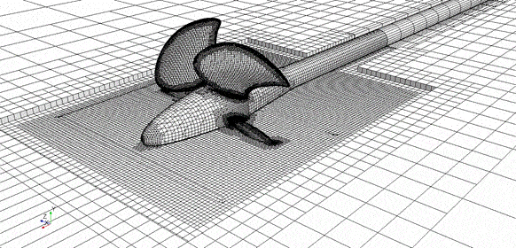
When we solve simulations of physical phenomenon, we discretize the real world geometry, its content and its surrounding environment with a mesh. Having the right mesh is vital and decides over defeator success of your simulation. So, with a good mesh you can both save computational cost, and get almost half-way to a correct solution. Let´s have a look at Simcenter STAR-CCM+ custom mesh controls and what tool (by MARIN) you can use for a mesh uncertainty analysis.

Custom Mesh Controls
First of all the mesh that we want to create is chintzy when it comes to number of cells, adapted to the flow and is fitted for the geometry. To achieve this, we have an extensive toolbox of different meshing approaches is Simcenter STAR-CCM+ (like Trimmed Mesher, Polyhedral Mesher, Prism Layer Mesher, Extrude Mesher, Directed Meshing, or Thin Mesher). However, in today´s topic we´ll focus on the Custom Mesh Controls only.

Custom Controls can be added to the Automated Mesh to achieve different levels of discretization in your domain based on part curves, part surfaces, and specified volumes. And override any default controls for the surface and volume meshers.
There are some things to keep in mind when defining Custom Controls.
1. Surface mesh matters
The mesh on the surface will be related to the geometric surface mesh (tesselation). You can control the tesselation either on the geometry at import or the Re-Tesselate command. Or alternatively with the Surface Remesher with adds 4 more controls to the default controls. See picture below for meshed appearance to the left and (underlying) tesselated geoemtry to the right.


2. Custom is King
Custom Controls overwrite the Default Controls. In the example below a Custom Control is introduced that restricts the surface size to 50 % of Base Size and revokes the Curvature control of the Surface Remesher (Default Controls).

3. The smallest once are in control
In case you define conflicting Custom Controls, the smallest control is enforced. Below, we have the Minimum Surface size as in the example above (overwriting defaults), however, the Curve Control prevails it´s Target Surface size of 25% along the curve.

4. Part Hierachy
Surface and Curve Cunstom Controls depend on the selection in part hierachy. You can either select single curvs/surfaces, the higher level Part, or a composite part that includes the part curves.

5. Tip: Use the Surface Remesher
For better representation of the geometry, always use the Surface Remesher. There are two occasion!
a. Mesher > Surface Remescher
In order to improve the overall quality of an existing surface and optimize it for the volume mesh models, the surface remesher can be used to retriangulate the surface.
b. Custom Control > Volumetric Control
The Volumetric Control allows for local surface remeshing when Surface Remesher is selected. The figure below shows the difference particularly on the underlying geometry representation.

Uncertainty Analysis
Once we have come up with a suitable mesh, we have to accept that our solution will still be erroneous because of this discretization, machine precision and statistical as well as iterative errors. The good thing is that the numerical errors can be verified by estimating an uncertainty interval within the error probably falls.
MARIN provides an easy tool to analyse your CFD results to
- estimate the iterative error, and to
- estimate the discretization uncertainty.
This can be very useful to confirm the choose mesh for application. The only extra work you have to do is to set up a simulation parameter for the mesh base size and a Design Manager Sweep Study which alters the parameter. A suitable test case can be the tutorial Steady Flow: Backward Facing Step. Here we use three meshes with varying base size from 0.4 to 0.1 for the finest mesh and monitor the pressure drop between inlet and outlet.


The pressure drop as a function of relative step size, defined as ![]()
in figure above, suggests an asymptotic convergence of the obtainable solution towards a non-error solution. For this case the mesh related uncertainty is calculated with 1.2%.

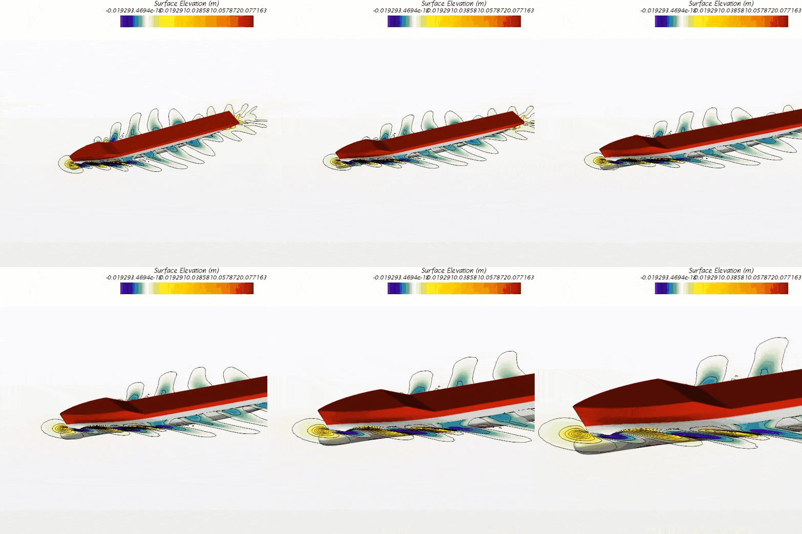
For marine applications this is interesting. Because the Virtual Tow Tank template for calm water resistance kind of includes a mesh dependency study with the Multi Mesh Sequencing. The goal of the MMS to speed simulation up convergence by solving on a coarse mesh and subsequently increase the mesh size and accuracy. However, the intermediate results at the mesh sequence can be reused to estimate the mesh uncertainty with MARINs Verfication tools. In this case I used the model scale simulation of the KCS container vessel. The mesh related uncertainty is calculated according to MARINs tool at 1.6 % for the final mesh sequence in the VTT.
We at Volupe hope that this blog post will help you in your mesh setup and assessment. For more details on the other uncertainty calculation and the other verification tools by MARIN, please be referred to their publication of VERIFICATION TOOLS. If you have any questions you are always welcome to reach out to us at support@volupe.com.
The Author
Florian Vesting, PhD
Contact: support@volupe.com
+46 768 51 23 46


