In this week’s blog post we will look deeper into meshing within Simcenter FLOEFD. A mesh is a discretization of the computational domain where the flow field information will be stored. The mesh will be built of many cells, and information about the flow will be stored in each cell center. The finer the mesh (higher number of cells, and with smaller volume), the higher resolution (less averaged) of the solution for the physical problem. A finer resolution will lead to longer computational time though, so it is good to know how fine resolution is needed. This blog post aims to give you information about how the mesh settings work and how the software uses the mesh, which hopefully will help you choosing the best settings for your discretization of the domain.
How Simcenter FLOEFD uses the mesh
The mesh cells in Simcenter FLOEFD are rectangular parallelepipeds (cubes if all sides are equally long) with faces that are aligned with the Cartesian coordinate system. A tip can therefore be to make sure your geometry’s flat surfaces are aligned with the axes of the coordinate system. Cells that are covering a boundary/wall are split, like in the picture below. In the picture you see cells as squares with dots where the cell center is located. The red line is representing the original curvature of the geometry, which is dividing the cells near the boundary with straight lines. For the split cells there is one cell center on each side of the boundary.

In CFD simulations the cells near a wall are always of extra interest, since the velocity gradients in this region are large. The velocity at the wall is zero and close to the wall the velocity profile increases exponentially. To capture these gradients, you usually would like to have several thin cells close to the wall, but in Simcenter FLOEFD this is not needed since wall functions are used. Wall functions are using experimental data to describe the flow close to the wall, instead of calculating the flow in this region. The wall functions used in Simcenter FLOEFD are dependent on how many cells that are used to cover the boundary layer. The boundary layer is the fluid flow closest to the wall, where the velocity goes from zero (at the wall) up to free stream velocity. If the cells needed to cover the boundary layer are:
- more than five a thick boundary layer approach is used – if the boundary layer is laminar a modification of the parameters in Navier-Stokes equations are used and if the boundary layer is turbulent equations from Van Driest are used in this region.
- less than five, thin boundary layer approach will be used – if the boundary layer is laminar Prandtl equations are used with Shvetz trial functions and if the boundary layer is turbulent Van Driest mixing length hypothesis are used.
- exactly five cells cover the boundary layer a mix of the two approaches is used to ensure a smooth transition between the methods.
Mesh settings
The settings for defining the mesh are done at the mesh node in the tree structure, the picture below visualizes the mesh node icon.

Here you can modify the global mesh settings, and also create local mesh refinements. In the global mesh settings, there will be two ways of defining sizes for the mesh cells, automatic and manual. Let’s look at the automatic control first, where you basically only specify the mesh size with a refinement level from 1 to 7, where 7 is the finest refinement level.
 The level of initial mesh indicates the number of cells used to discretize a specific length in a certain direction. The number of cells for a specific refinement level can be found in the table below.

In the global mesh settings, you can also activate advanced channel refinement, where you can define a distance which will resolves all channels with larger thickness than the specified value, with enough number of cells.
Now let’s go further and look at the manual settings. The manual settings are the actual settings used for defining the meshing. The automatic mesh settings are just a simplified way of defining all the settings in the manual settings. If the automatic settings are changed, the manual settings will follow, but not the other way around. If you reset the manual settings to the settings corresponding to the automatic settings, you can always Reset to manual settings via the button in the bottom of the picture below.
In the picture above you see several manual settings with either levels from 0 to 9 or the possibility to specify a value. The settings are:
- Basic mesh – number of cells in each direction: Defining the number of cells per length in each direction. A possibility to enable aspect ratio for cells to be kept is available, meaning that you will only change one direction and the other will be scaled according to the initial mesh.
- Refining cells – volume cells: Defining a level from 0 to 9 of how fine cells will be in the free flow.
- Refining cells – boundary cells: Defining a level from 0 to 9 of how fine cells will be at the boundaries/walls.
- Channels – number of cells across a channel: Selecting a number for how many cells should resolve a channel.
- Channels – maximum refinement: Defining a level from 0 to 9 of how fine cells are allowed to be in a channel.
- Channels – minimum/maximum height of channel to refine: Possibility to enable specifing dimensions for channels to refine. Defualt is disabled.
- Advanced refinement – small solid feature level: Defining a level from 0 to 9 of how high resolution you want on small features. Cells will be split to capture small features in the level is high enough to resolve the feature. If the refinement level is not high enough to split the cells around the feature, the feature will not be considered in the simulation. The feature will only be resolved if it fulfills the 120-degree-criterion, meaning that the normals of the sides of the feature need to be within 60degrees and 120degrees.
- Advanced refinement – curvature level: Defining a level from 0 to 9 of how curved features have to be to be able to split cells, and therefore capturing the feature better.
- Advanced refinement – curvature criterion: Specifying a value for which curvatures to resolve, where a higher value includes more features to be resolved. A value of 3.14radians allow normal on faces to be up to 180degrees and still be able to split cells.
- Advanced refinement – tolerance level: Defining a level from 0 to 9 of how the refinement level should tolerate the size of solid parts that are about to split cells.
- Advanced refinement – tolerance criterion: Specifying a number for the size of solid parts to be able to split cells according to the tolerance.
- Close thin slots: Specifying a maximum value for thin slots, which will be closed. No mesh will be created in these slots, so the equations will not be calculated here.
- Display refinement level: Here you can display, via a grid which is appearing in the scene, how the cell size corresponding to a specific refinement level will be.

Local mesh refinement
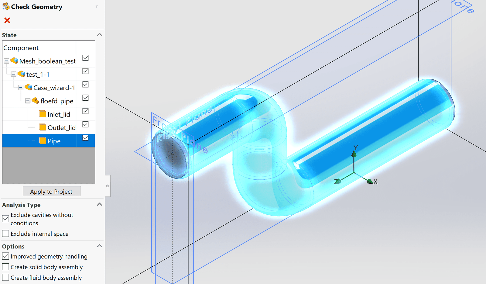
When adding a local mesh refinement, the mesh settings are applied in the same way as for the manual mesh. The two pictures below show how the location of the local refinement is chosen, either by selecting location corresponding to a part (left picture) or by defining a geometrical shape (right picture). For the geometrical shape there are pre-defined shapes to use.

One thing to notice is that the local mesh refinement will override the global mesh settings even though these settings will lead to a coarser mesh. This means that you can create a local coarsening of the mesh, if the global settings are not already at the most coarse setting.
Visualization of the mesh
To display the mesh you have created you can create a mesh scene. This post-processing option will be available even if you have only created the mesh and not run the solver. To create a mesh scene, click on the icon in the tree-structure according to the picture below.
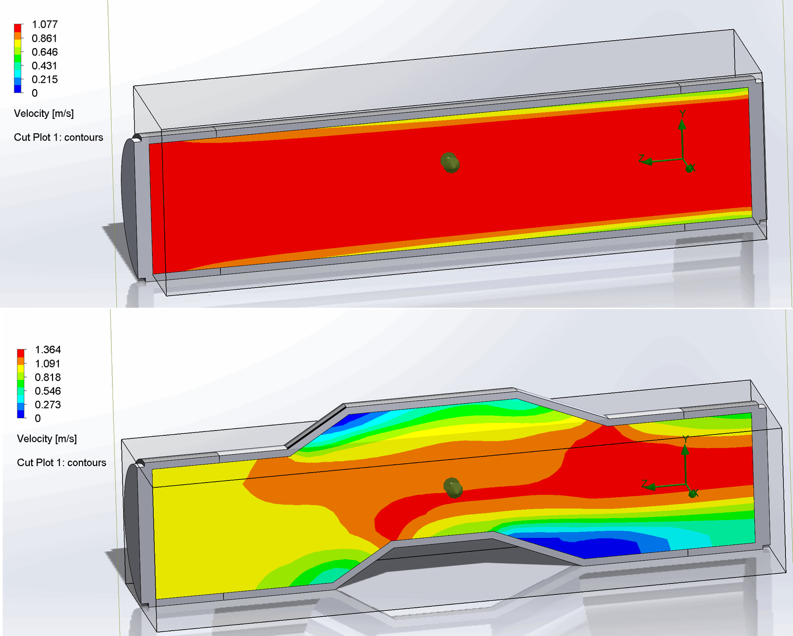
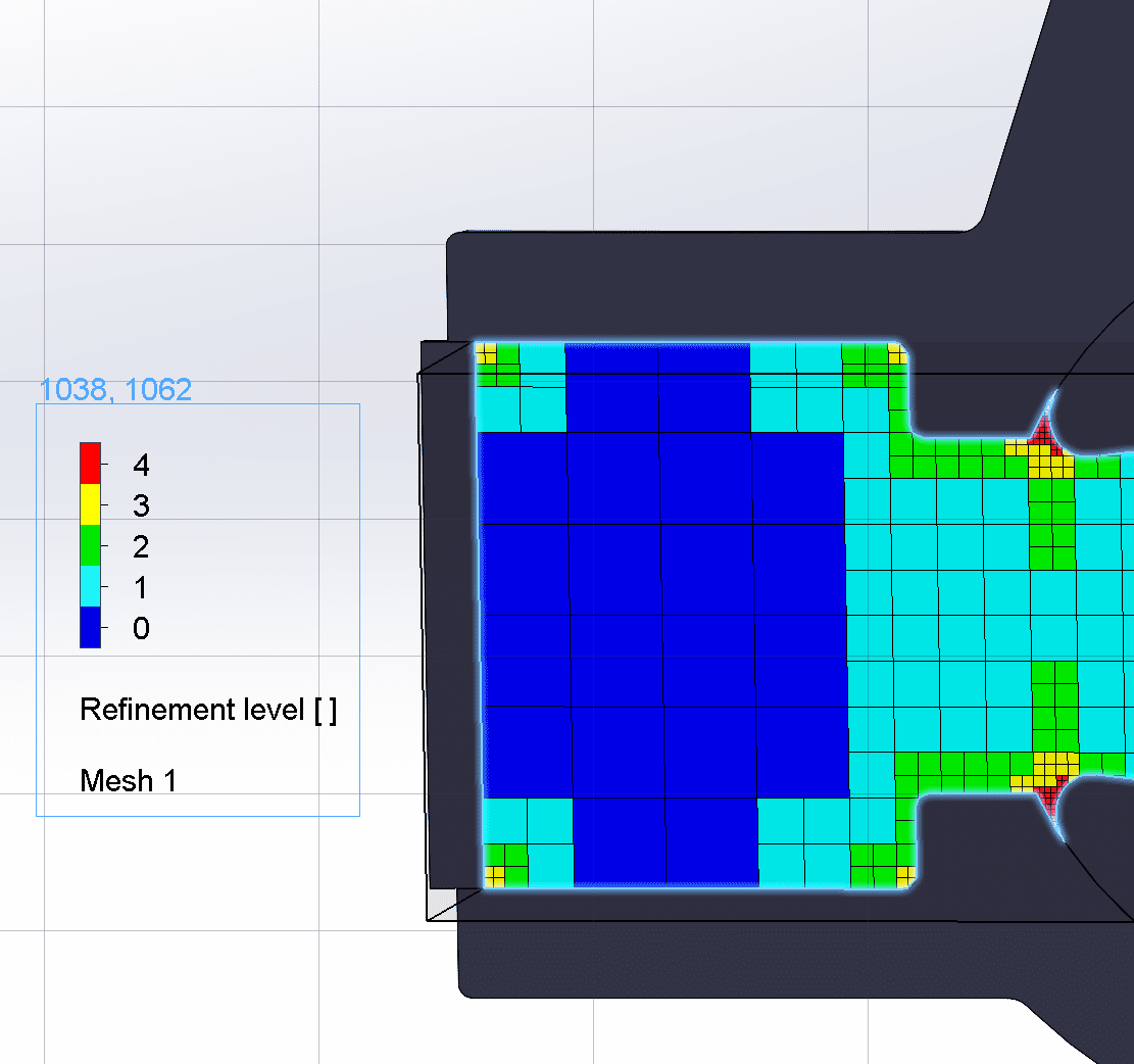
 The mesh scene will look like the picture below, for the actual example that is used for this blog post. Here you get information about which level of cells that are used in the mesh. In the picture there are 4 levels of refinement, where an increase in level by one indicates one cell split into eight cells. So, for each increment in level all sides of a cell is split in half. One rule of meshing in Simcenter FLOEFD is that a cell can only be next to a cell with maximum difference in refinement level of one, ensuring a smooth transition between cell sizes.

We at Volupe hopes that this blog post will help you with meshing in Simcenter FLOEFD. For more details there is further descriptions in the Technical reference attached to the installation file of the software. If there are any questions, or anything we can help you with, please send an email to support@volupe.com.
Author
Christoffer Johansson, M.Sc.
support@volupe.com
+46764479945