November has not only brought us overcast skies and colder weather, but also a brand-new version of Simcenter Amesim. Available for download at Siemens support portal, version 2021.2 has now come with some much-appreciated updates in regards to both features and capabilities.
This week’s post will attempt to cover and highlight a couple of the improvements recently made in the tool:
![]() The Battery Electro-Thermal Identification Toolbox
The Battery Electro-Thermal Identification Toolbox
![]() Ground Designer
Ground Designer
![]() Test Data Import
Test Data Import
The Battery Electro-Thermal Identification Toolbox
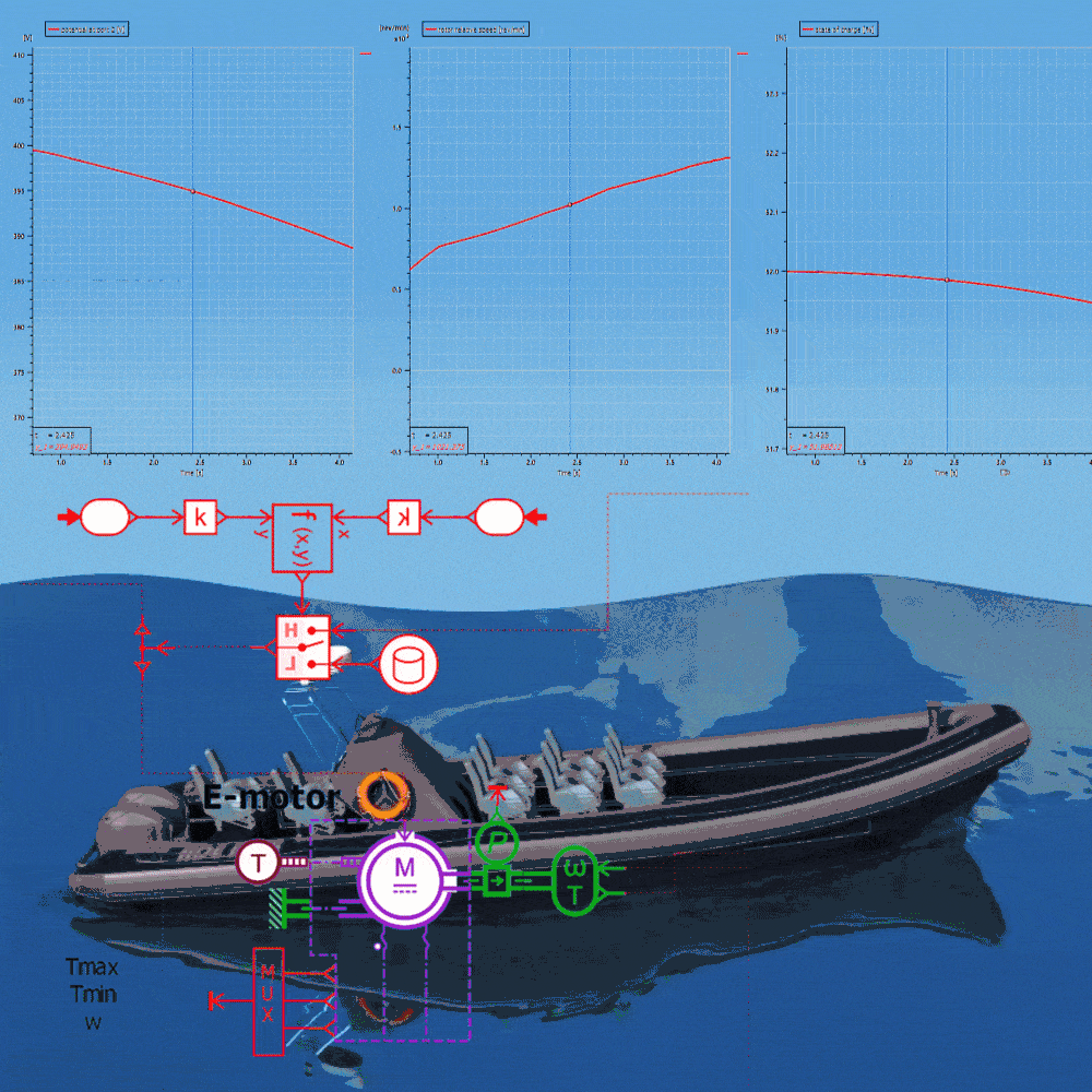
The Battery Electro-Thermal Identification Toolbox is a set of Python utilities conveniently packaged as a tool within Simcenter Amesim. The step-by-step method aims to simplify the process of modelling electrical and thermal behavior provided from user-supplied battery measurements of current, voltage, and temperature. The measurements can be obtained either from performing experimental tests on the battery, or from simulation using complex battery models such as an electrochemical model. By following the identification steps shown in the image below, the tool is able to identify and set necessary parameters belonging to the battery advanced equivalent circuit model. This can either be done on cell level or as a battery pack.

The procedure consists of several steps and includes calculations such as calculation of real capacity from test profiles, calculation of open circuit voltage at different State of Charge (SoC), determining ohmic resistance at different SoC, thermal model identification, etc. The results are then tabulated as functions of SoC, current, and temperature to be used and referenced during future simulation. An example of identified parameters is given below in table 1.

Ground Designer
While available in version 2021.1, the Ground Designer has gone through some larger updates in the most recent version to make it more user-friendly and robust. For those of you unfamiliar with what the tool/app does, it can shortly be described as a tool for quickly generating simplified custom terrain and is used together with other components in the Vehicle Dynamics library.
The template-based approach focuses on steep and uneven ground which is of particular interest for off-highway vehicles typically found in the construction, mining, agriculture, and forestry industries. In addition to adding bumps and depressions, altering inclination, and modifying path settings, the Ground Designer’s final road model can also be combined with behavior for soft soil. By connecting the tire model for soft soil with the road grip model and the terrain, it is possible to investigate and estimate the impact of driving on soft and uneven ground on the vehicle and its subsystems.
It should be stated that the interaction and contact forces between a tire and soft soil is complex. Modeling it in greater detail would require obtaining a large set of parameters values which could be difficult and time consuming to identify. Instead, the modelling approach chosen with this implementation is the opposite, to make the best use of parameters you can reasonably obtain: tire dimension and a measure of soil hardness.
The current version of ground designer makes use of template files for the general definitions, such as number of bumps/depressions and the overall shape of the road. Users are free to modify these .txt files and to for example include more obstacles. The templates may be found by navigating to File –> Load Template, “then onwards to the installation directory” and Amesim/libdv/utils/GroundDesigner_toolbox/resources/templates/roadWithSTurn.txt.

I freely admit this is a bit of a hassle, and the features should have been integrated in the tool itself alongside the other settings. Hopefully we will see this in the upcoming versions. Regardless, modifying the .txt files is fairly straightforward and rows can be added and excluded. Once the .txt file has been modified, changing location and dimensions of obstacles can easily be done with the parameterized parameters inside the tool. Thereby allowing for quick generation of different driving scenarios in mass.
The final ground mesh is generated as an .obj file and used together with the Ground Description object VDGROUND0. In the following animation, I have made some alterations to the ground mesh using the open-source 3D graphics software Blender and imported the resulting .obj file into a slightly modified version of the Articulated dump truck demonstrator model.
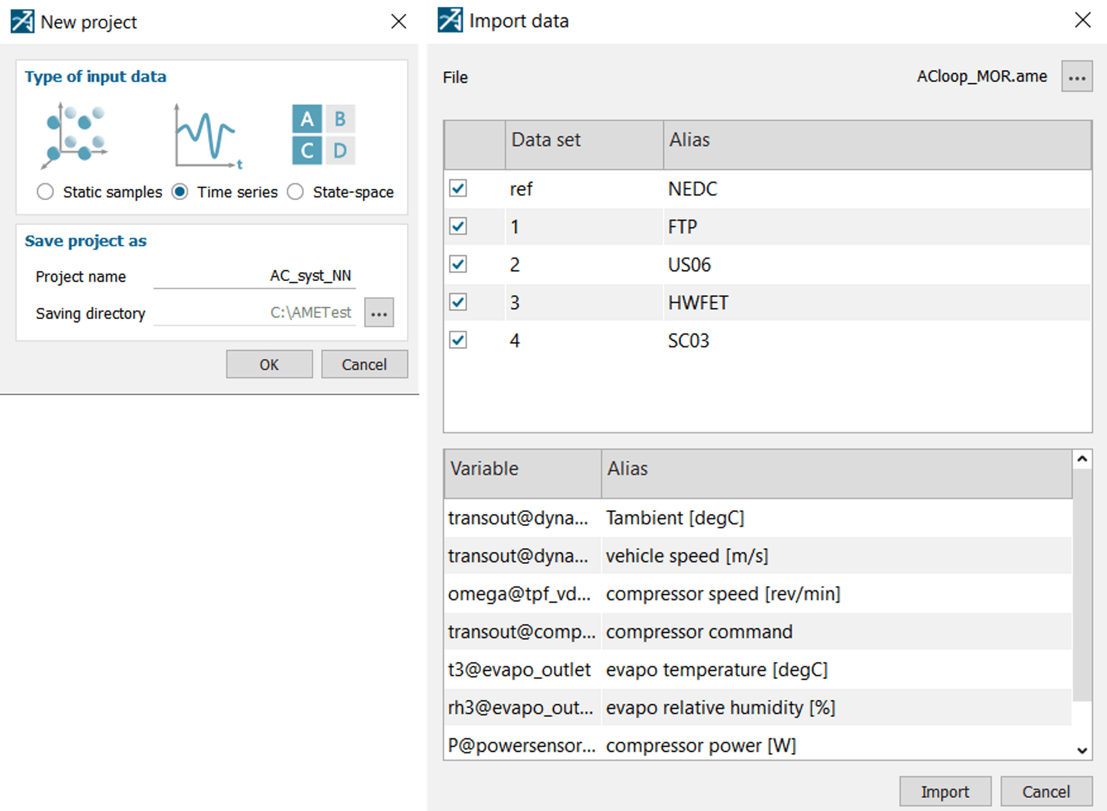
New Test Data Import App
A common situation one encounters when working with system simulation is related to importing and managing test results. Generally, importing and using test data can become quite tedious if multiple sensors are involved. Therefore, a new app has been made available in version 2021.2 to alleviate the cumbersome processes of importing and connecting sensor data to a simulation model. The app, named Test data import, makes use of the preexisting Data import tool to create and automatically connect a dynamic table (dynamic_x_table) with the necessary number of transmitter and receiver objects specified by the test data. The imagery below exemplifies how to make use of this new feature.

To experiment with, and stress-test, this feature a larger set of randomized values was created in an Excel spreadsheet. The table used 130 individual sensor names, each with a corresponding column of 10 000 values. Consequently, a table of 1.3 million individual values.

Inside Data Import, setting the first row as title allows the final supercomponent to use the correct sensor names. In my example this was done by right clicking the first row and selecting: Set as “Title row”. Once the Data import step is complete the user is offered the option to select time as input and whether the table is to be embedded in the current simulation file. When clicking the ok button, Simcenter Amesim automatically creates the supercomponent in Sketch mode in an iterative manner. For the larger table described above the process took a few minutes to complete and did not run into any issues when creating the component.
Test data import offers flexibility when importing larger datasets and is a convenient tool to use if the structure of the measurement data changes.
Hopefully you found this post worth a look through. If you have any questions or comments related to the topic, or regarding simulation in general, please feel free to reach out to us by emailing support@volupe.com
Author
Fabian Hasselby, M.sc.
+46733661021