Download the simulation files which correspond to the examples in this blog post:
[wpdm_package id=’7855′]
This week we will have a deeper look into the overset mesh workflow, more specifically for the case when there is a close proximity between walls with relative motion. In a previous blog post, Overset mesh in Simcenter STAR-CCM+, there were several tips included – on how to set up a simulation using overset mesh – which also touched upon the topic of close proximity. As mentioned in this blog post, Siemens have collected a Best practice video called Golden rules for overset mesh which can be good to look at as well.
This blog post will include a simulation setup of a rotating rod within a cylinder with stationary walls – to explain how to handle close proximity using the features in Simcenter STAR-CCM+. There are four example simulations:
- Case 1 – using ordinary overset meshing technique, where the rotating rod (and the rotating overset mesh region) is located far from the stationary wall.
- Case 2 – where there is a small gap between the rod and the stationary wall, and still using ordinary overset mesh technique (not overset zerogap mesh). Rotating region being close to the stationary wall, but not connected to the wall (using feature proximity and alternative hole cutting, see picture below for visualization of interface settings).
- Case 3 – where there is a small gap between the rotation rod and the stationary wall, using overset zerogap mesh. The rotating region covering the complete gap between the rod and the wall.
- Case 4 – where there is no gap between the wall and the rod (rotating region is all the way out to the wall), using overset zerogap mesh (the zerogap wall region changes location in every time step since the cylinder is not moving – using feature proximity and alternative hole cutting).
In the picture below you can see interface settings when using Close proximity and Alternative hole cutting for overset mesh simulations. Both these feature are handling problems that can occur when having boundaries that can become close to each other within the simulation via more robust algorithms for closing gaps.

Example 1 – overset mesh without close proximity
In the first example of this blog post you see the cylinder domain in the picture below, and inside it there is a grey rod that will rotate. The overset (rotating) domain is diplayed with a purple mesh and the background domain is displayed with a black mesh.
As you see in the picture there are more than five cells between the edge of the overset mesh region and the stationary wall. This means that you can use the ordinary overset mesh workflow, and no special features are needed. Note that the cell size is similar in the overset mesh and the background mesh as recommended.

Example 2 – overset mesh with close proximity (but no overset zerogap)
In the second example we have not resolved the gap between the rotating rod and the stationary wall with the recommended five cells in normal direction, see picture below. There can be several reasons why you do not have the possibility to resolve the gap properly, for example that this will make the simulation too heavy to run on your available hardware. This can be solved using the close proximity and alternative hole cutting features on the interface instead. Still using the ordinary overset mesh technique these features allow for the use of only two cells between the walls instead of the otherwise recommended five cells.

Note: this simulation could have been simulated using zerogap (without close proximity and alternative hole cutting) instead of using the ordinary overset mesh technique together with the settings close proximity and alternative hole cutting.
Example 3 – overset mesh with close proximity using zerogap
In the next example the overset mesh region is covering the complete gap between the rod and the wall, see picture below. Overset mesh with zerogap interface is used to allow the overset mesh region to cover the complete gap region. In this simulation the rotating rod is not in contact with the stationary wall so close proximity and alternative hole cutting is not needed. Overset mesh with zerogap interface is more stable than the ordinary overset mesh when having close proximity, so if you want to be on the safer side (in terms of simulation stability), zerogap interface can be used.

Note: this simulation could not have been simulated without using zerogap. Using overset mesh and the settings close proximity and alternative hole cutting cannot handle the rotating region to go all the wat to the stationary wall.
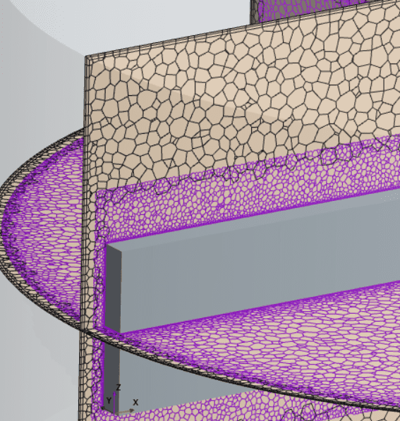
Example 4 – overset mesh with connected walls using zerogap
In the final example the rotating rod is scraping the stationary wall, leaving no gap between the surfaces. The overset mesh region is therefore also as broad as the background mesh, see picture below. In this case you must use overset zerogap since there is literally a zero gap (no gap). The features of close proximity and alternative hole cutting for the interface settings are needed here.

At the location where the rotating rod is touching the stationary wall the mesh technique will deactivate cells and temporarily store them in the boundary of ZeroGapWall. In the picture below you see that there are cells at the connection of the regions that are deactivated.

Note: We are not using the features of prism layer shrinkage or treat error as warning since these settings are not recommended to use at first tries – the simulation should be able to run even without these features if the setup was correctly implemented.
Summary
To conclude what we have discussed in this blog post, the following has been shown:
- When to use overset mesh (without extra features of zero gap and additional interface settings), for example when fulfilling the recommendation of having more than five cells between boundaries with relative motion.
- Close proximity and alternative hole cutting can allow using as few as only two cells between the rotating region and the stationary boundary.
- Overset mesh with zerogap interface allows for having the overset mesh region and the boundaries in contact.
- How overset zerogap deactivates cells if contact occurs.
- The settings of prism layer shrinkage and treat error as warning should not be used.
Don’t forget to download the simulation files for the four different examples via the link in the top of the page if you want to investigate the settings in more detail.
We at Volupe hope that this blog post will help you in your overset mesh simulations and how to decide your interface settings depending on how close your walls are located. If you have any questions you are always welcome to reach out to us at support@volupe.com.
Author
Christoffer Johansson, M.Sc.
support@volupe.com
+46764479945