In projects where simulations are performed there is often a need to investigate changes in results due to changes in the product, like design exploration. These changes can be geometrical, investigation of performance at different flow conditions, and/or aspects of how well you are approximating the geometry in terms of the mesh. In this week’s blog post we will go through which options there are in Simcenter FLOEFD to vary these changes in your simulations:
- Manual changes by cloning your projects
- Parametric studies for flow conditions and mesh settings
- Geometrical changes
Manual changes by cloning your projects
To not have to start all over again when changing some minor setting in your simulation the feature of cloning your projects – and then change your settings – will save you time. This way will allow you to have several projects set up in the same assembly (simulation) file. You can then run these projects in batch mode to get all results with just one click.

Parametric studies for flow conditions and mesh settings
The method described above is useful, but when the need to change the mesh settings (in for example a mesh independency study) or flow conditions arise, this can instead be done in an easier way – using a parametric study. A parametric study can be activated for one project, and after it is performed all the results can be displayed directly in the GUI (without changing which project that should be active). The picture below shows how to create a parametric study within your project.

As an example, the picture below shows the parameters that can be set in a simple pipe flow simulation. The possible parameters will be added automatically based on your settings in the project. As you see in the picture below there are many parameters possible to change already in this example, if you add more complexity to the project there will be even more parameters to investigate.

If you want to dig deeper into parametric studies, there are two great tutorials available as Parametric study examples in the Tutorial guide that comes with the installation of Simcenter FLOEFD:
- F1 – Design Optimization
- F2 – Calibration
Geometrical changes – example with changing a straight pipe to a bent pipe
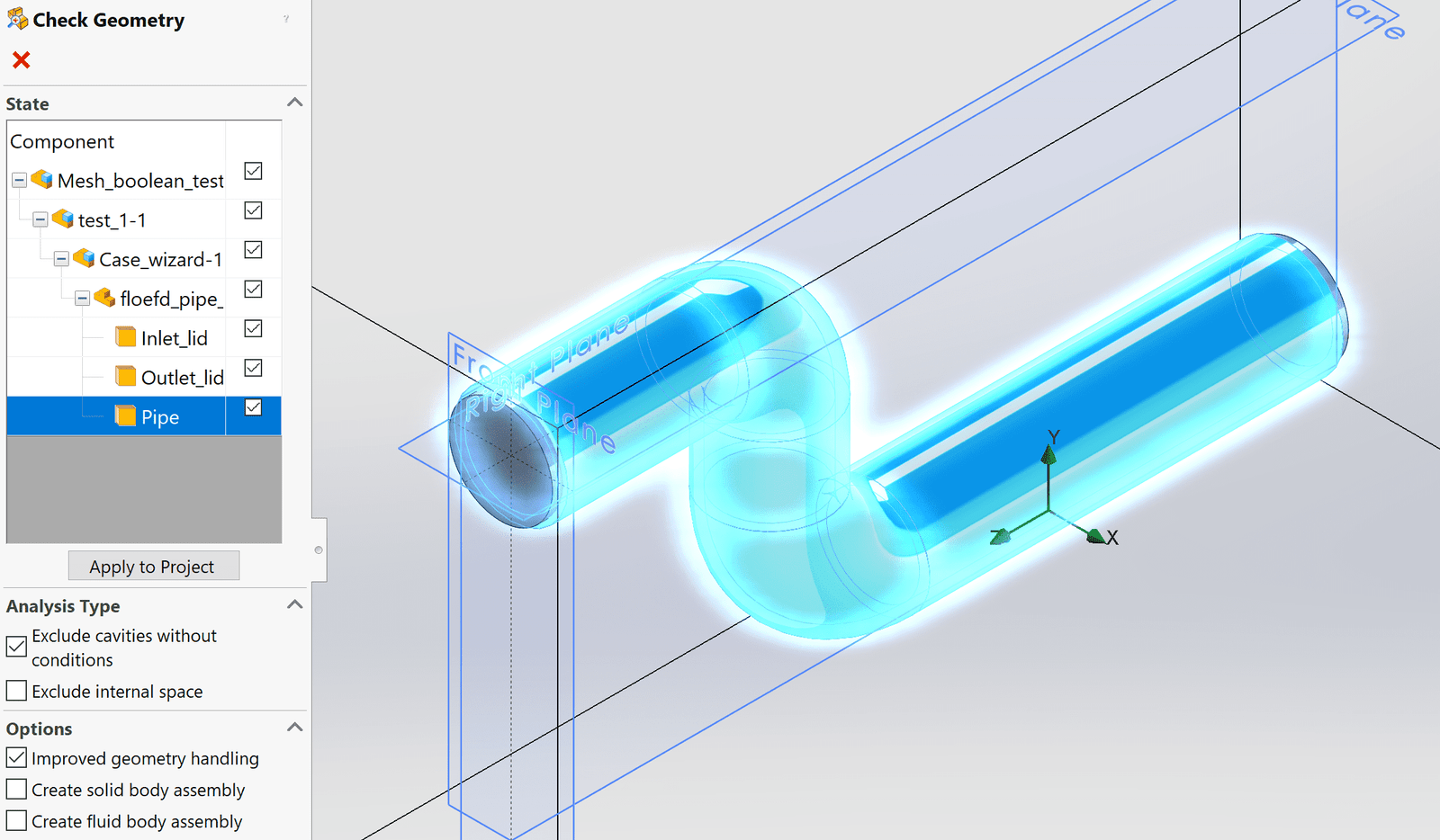
If you are interested in investigating how geometrical changes affect the results of the simulation, you can still do this within one assembly (simulation file) if you import all parts in the assembly and suppress the parts you are not interested in at the moment.

In the Component control you can also manage which parts are active.

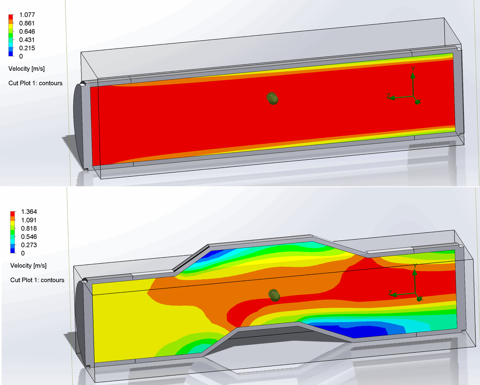
In this example we are looking at a pipe which is split up so the middle part is possible to exchange (the middle part is highlighted in blue in the picture below).

After the results are calculated for the straight pipe we need to clone the project and then suppress the straight middle part and unsuppress the bent middle part instead.

Since there will be no change in boundary conditions between these two projects, in this simple case, we only have to think about the size of the fluid domain changing. Simcenter FLOEFD will let you know if there has been changes in the fluid domain, and it is always recommended to use the Check geometry after changes has been made.
When changing the geometry the computational domain can end up being outdated, giving error messages in the tree structure as in the picture below. To solve this, simply activate one other project (right-click and the select activate) and then activate the project of interest again so it is updated and the simulation tree should be shown without any error.

The results can then be visualized as usual, see picture below for the straight pipe.

After activating the project for the bent pipe (and suppressing/unsuppressing the geometry if you also want the geometry to be updated in the GUI), you can get the results of the other project as well.
We at Volupe hope that this topic has been of interest to you, and that it will help you save time and effort when running multiple simulations with similar settings in Simcenter FLOEFD. If you have any questions, you are always welcome to send them to us at volupe@support.com.
Author

Christoffer Johansson, M.Sc.
support@volupe.com
+46764479945