This week, we will look at radiation, focusing on S2S (surface to surface) radiation in Simcenter STAR-CCM+. We will look at some things to consider when including radiation, how to use it efficiently and how to understand it. We will also go over the different radiation models in Simcenter STAR-CCM+ to understand when to use them, and when not to use them. But first, a brief theory section on radiation.
Radiation
All objects absorb and emit electromagnetic radiation. An object’s ability to emit radiation is determined by its colour. Black bodies are the most efficient in emitting radiation, while white objects are the least effective. Most objects have different abilities to emit and absorb radiation at different wavelengths. This aside from a Gray body, that has radiation properties that are independent of wavelength. Any body’s radiation is determined by the Stefan-Boltzmann law of Radiation:
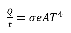
Where σ=5.67 x 10⁻⁸ J/s * m2 * K is the Stefan-Boltzmann constant. A is the surface area of the object, and T is the absolute temperature in Kelvin. The e, in the equation, is the body’s emissivity. Assume we want to use this equation in an example; let us consider a person with a surface area of 1.60 m2, standing in a dark room, having a normal surface temperature of the 33°C and the room is at 20°C. The emissivity of skin is 0.97. We then calculate the net rate of heat transfer by radiation, which is given by:

The negative sign before the value, indicating that the radiation is leaving the body. Heat is radiating FROM the person.
What is also good when working with radiation in Simcenter STAR-CCM+ is to remember the following terms:
Absorbtivity – A measure of how much radiation is absorbed by a body.
Emissivity – A body’s ability to emit radiation.
Reflectivity – A surfaces ability to reflect radiation.
Transmissivity – A surface ability to let radiation through.
The theoretical relationship for these properties is:
Absorbtivity + Reflectivity + Transmissivity = 1 (for a given wavelength)
Note however that in Simcenter STAR-CCM+ it is assumed that Absorptivity and Emissivity are equal, meaning that all radiation absorbed by a body is also emitted by said body. This assumption is made under Kirchhoff’s law of thermal radiation, saying that; “For an arbitrary body emitting and absorbing thermal radiation in thermodynamic equilibrium, the emissivity is equal to the absorptivity”. This means that radiation Absorptivity is not something you specify (Absorbtivity=Emissivity), hence for Simcenter STAR-CCM+:
Emissivity + Reflectivity + Transmissivity = 1
Radiation models in Simcenter STAR-CCM+
When it comes to simulating radiation in Simcenter STAR-CCM+ there is a division between Surface radiation exchange and Volume radiation exchange. The later example (see section Our example) will focus on surface radiation (S2S), but it is first important to describe the differences between these two methodologies.
Surface radiation exchange
Surface-to-surface Radiation (S2S) – A deterministic method using view factors calculated beforehand. Adds several linear equations at the end of each iteration to solve for radiation heat transfer.
Surface Photon Monte Carlo (SPMC) – A statistical model that solves radiation using ray tracing. This model is more advanced and computationally expensive than S2S and can take refraction into account.
Volume radiation exchange
The media can absorb, emit, or scatter thermal radiation. You can include particles from a Lagrangian phase or use the soot emission models.
Participating media radiation (DOM) – using the discrete Ordinates method, where the angular representation of the space around a cell is most important and can be given different orders.
Participating media (Spherical Harmonics) – Here harmonic functions are used to model radiation intensity gradient in the medium.
Our example
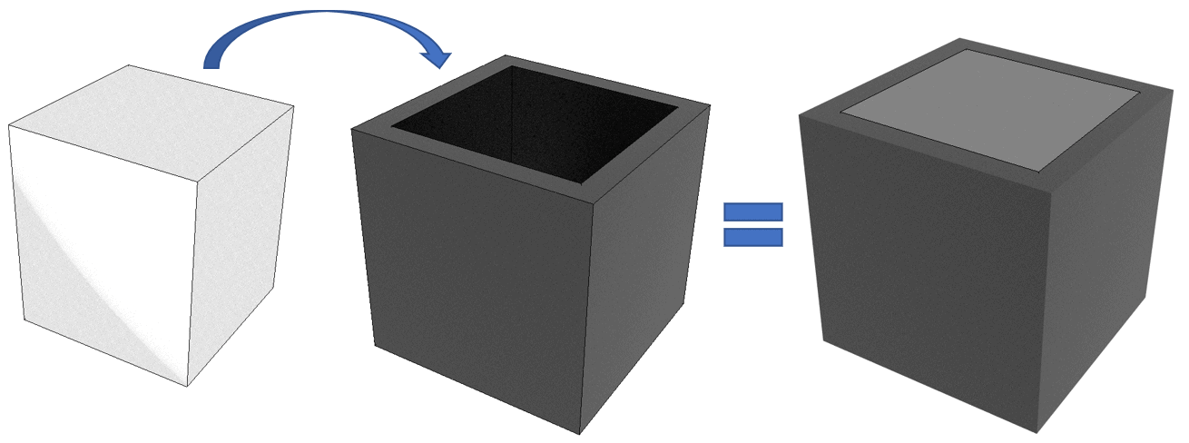
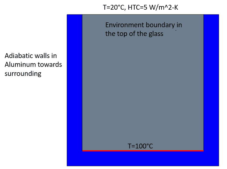
After a brief theoretical section and a short description of which models are available in Simcenter STAR-CCM+ we will focus on S2S radiation, and gray thermal radiation. The example we will look at is a glass box submerged in aluminium. The aluminium box is completely adiabatic towards the surrounding, no heat can leave the system via the walls of the box. The only heat transfer possible is via the glass surface on the top.
The ambient temperature is 20°C. S2S radiation is activated for the glass cube and the Internal radiation option is ticked in for the region since we are dealing with a solid. The interface, between the bottom of the cube and the aluminium sharing that location, has a temperature of 100°C. This is the only heat source in the domain.
The issue we will look at later has to do with how to account for radiation when allowing radiation to leave the domain, alternatively entering the domain. But first some notes on the View factors calculation performed.
View factors and radiation patches
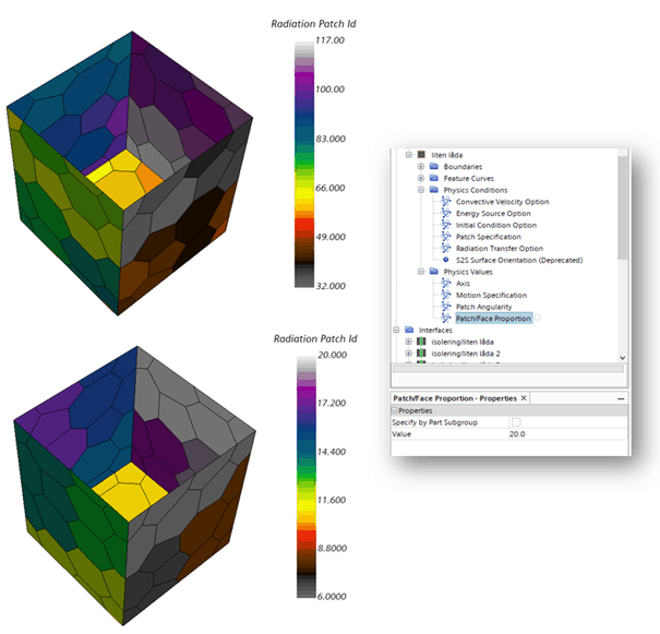
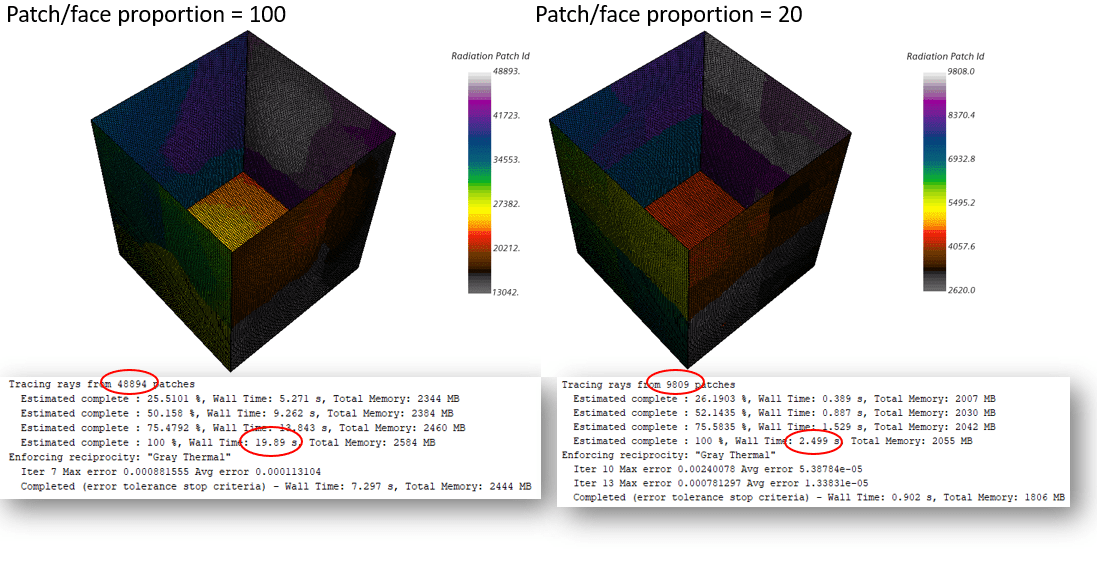
The S2S radiation model uses view factor calculation prior to running the simulation. This is a computationally expensive process, but it is only needed to be done once (given the mesh and the computational domain remain the same during the simulation). There are ways to speed up the view factor calculations. The default settings for radiation patches are 100, meaning that the patch/face proportion is 100 % and each face gets 100 % of a patch. With this setting, all the faces in your mesh will have separate patches. Setting a value instead, for example 20, the target is instead to give a face 20% of a patch, then each patch instead covers five faces. This can be seen in the picture below. In the top figure each face is given its own radiation patch, while in the lower one, several faces share the patch id:s (note also the difference in scale for the different cases 21 vs 118 patches).

This will reduce the time it takes to calculate the view factors. Below, are figures from a case with much higher resolution, than the example above. In the example below the face/patch proportion is reduced from 100 to 20 again. The output window shows the number of patches and the time it takes for the view factors to be calculated. We reduce the time it takes from about 20 s to around 2.5 s. Note however that the resolution of the patch/face proportions reduce the accuracy of the solution, just as with mesh resolution. The level of reduction you can use will be case specific, both in terms of resolution and relevance of the radiation physics.
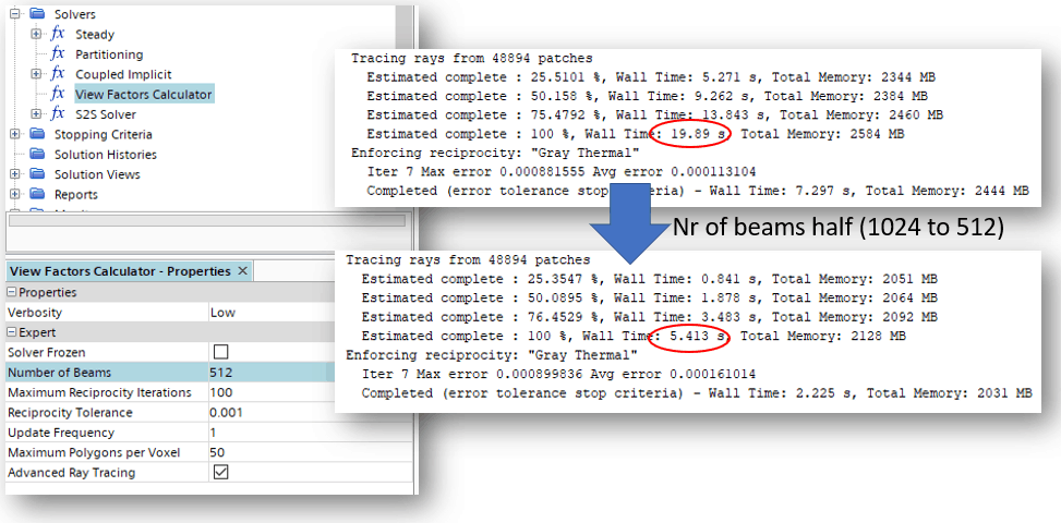
Another thing to reduce is the number of beams in the view factor calculator. This will reduce the accuracy of the view factors but will also speed up the view factor calculation. Using the patch/face proportion of 100 from the example above, we will now use half the number of beams to see that we end up with a calculation that takes one quarter of the time.
Simulation result for environment boundary condition
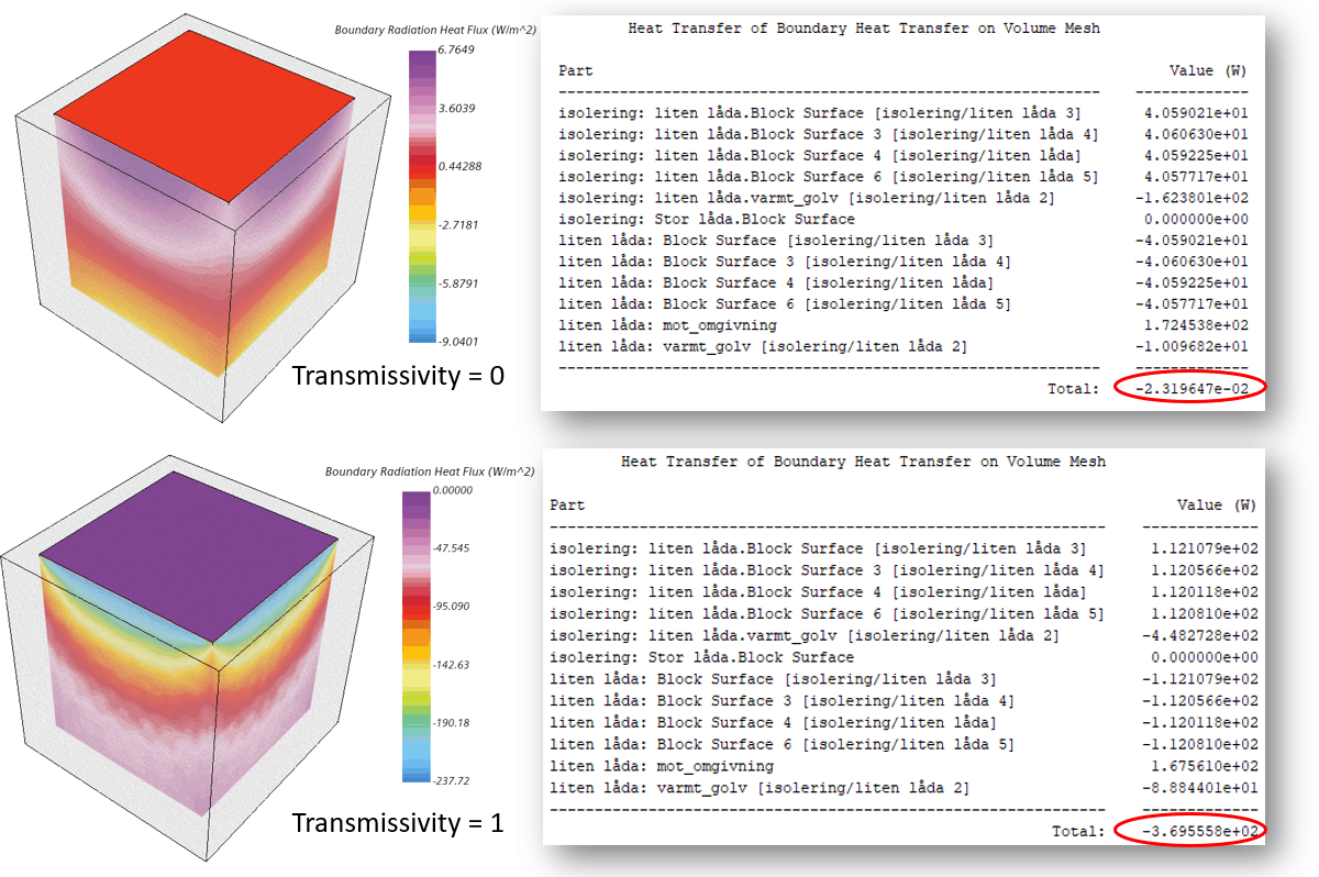
The last thing I would like to raise in this post is the fact that there might be some questions in terms of energy balance when you use an environment boundary condition. Using the previous example set up, we will compare the results from a simulation with full transmissivity (1) and full reflectivity (transmissivity = 0). In a closed system the energy balance should sum up to 0, meaning all heat entering the domain is also leaving the domain, we do not have accumulation of energy (Kirchhoff’s law again). For the case where transmissivity is set to zero for the top surface, this is true. The picture below shows the summation of heat transfer on all active boundaries and interfaces. The value shown is almost zero (-0.02319 W) but is at this point representing the error of the calculation rather than accumulation of energy. Instead looking at the case where transmissivity is set to 1, the energy balance shows a large negative value. (-369 W). Why is this then? Does this mean that we have a never-ending loss of energy in the system at transmissivity=1? No, that is not the case, the environment boundary condition is used in Simcenter STAR-CCM+ to balance out the energy equation. It is visible from the picture and from the scale, that since the temperature is higher in the box than outside of it, all the inside boundaries radiate out from the domain when transmissivity=1. This will lead to a negative value of the energy balance. As described above, that is however not the case when no radiation is allowed outside of the domain.
This is only a small chunk of what can be learned about radiation and the Simcenter STAR-CCM+ models. You can find more information in the documentation and at support center. I hope this has been a useful article. And as usual do not hesitate to reach out with your question to support@volupe.com.
Read also:
Simcenter STAR-CCM+ version 2020.3 news – Part 2
How to transform Display views
How to run a basic simulation in Simcenter FloEFD
Advanced Rendering in Simcenter Star-CCM+
Directed meshing in Simcenter STAR-CCM+


